-
Notifications
You must be signed in to change notification settings - Fork 12
Home
A bicycle wheel (composed of an aluminum rim and stainless-steel spokes, and steel axle) is mounted on a wooden plank.
The sensor and associated circuit board is lashed to the spokes near the rim, with the sensor about 24cm away from the ferromagnetic materials in the axle.
A counterweight is attached to the wheel opposite the circuit board so the wheel can rotate freely and without excessive imbalance.
- Intermittently the output from the filter function will drift steadily and continuously away from the known heading, even when the sensor is held stationary.
Example as observed by tedenda:

It is not believed to be caused by lack of calibration, as it has been seen after calibration.
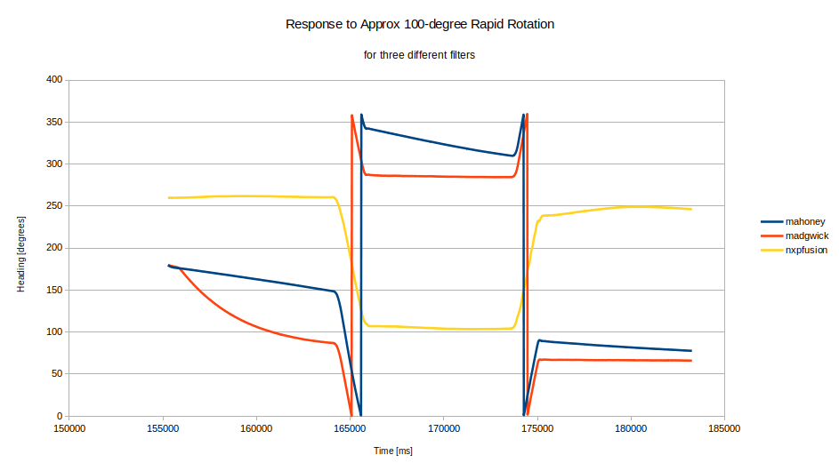
Overshoot and undershoot is observed in the filter's Heading output when the sensor is exposed to a quick rotation. In the following graph, the heading output computed by three different filter algorithms is plotted while the test fixture's wheel was manually held stationary, then rotated quickly by about 100 degrees, held stationary, then rotated back to the approximate starting position.

The under/overshoot seems much greater in magnitude than expected. See for example the discussion by Kris on (https://github.com/kriswiner/EM7180_SENtral_sensor_hub/wiki/K.-Limits-of-Absolute-Heading-Accuracy-Using-Inexpensive-MEMS-Sensors). His apparatus does differ from my wheel: his sensor is mounted coaxial with the fixture and therefore would report very low accelerations while being rotated. Also, his method did not involve a quick step motion, rather he measured position at multiple stationary points with (presumably) the filter output settling after each motion. However, on a vessel it will be critical to respond correctly to abrupt surges/rolls/pitches etc. Regradless, Kris' results suggest that we should be able to achieve accuracy within 2 degrees and currently we see +/- 10 degrees or worse.
- sometimes get much worse over/undershoot.
- not caused by exceeding maximum rotation speed gyro can report (currently 250 degrees/sec)
- doesn't seem to be caused by incorrect scaling of the gyro output, as a separate test in which the wheel was allowed to freely rotate showed that the rotation reported by the gyro corresponded within ~3% of the rate measured by a position sensor located on the rim of the wheel.
- the sensor defaults to not using the built-in 32-sample FIFO - i.e. the measured rotations are realtime, not buffered. So it does not appear to be caused by a temporal lag between actual motion and measured motion.
- TODO: test at max sensor rate (800 Hz)
- TODO: test filter using synthetic data
- TODO: test other filters if available
- TODO: test with sensor coaxial with rotation axis
- TODO: see if there is a rate-dependence on the error
- TODO: the filter file
Adafruit_AHRS_NXPFusion.cppcontains a lot of constants for parameters like sensor noise and drift. Are these set to optimum numbers for the FXAS21002C?
Using the Adafruit AHRS code, which in the source indicates it is derived from https://github.com/memsindustrygroup/Open-Source-Sensor-Fusion/ This location has lots of info, including that it is based on Freescale's version 4.2.2 Sensor Fusion library. NXP now has version 7.0.0 released.
In Resource 6, NXP says "...the equations of motion at the heart of this and many other fusion-based systems assume that all quantities are measured at the same moments in time. This may not even be possible to do, as there is no common set of sampling frequencies that apply to all sensors.The easiest way to deal with this problem is to ignore it via the simple expedient of polling all sensors at a fixed rate, while setting their internal sample rates high enough that you can ignore any sample time jitter. You might even want to sample at a much higher rate so that you can filter raw sensor samples to reduce noise. This approach has been taken by all prior versions of the sensor fusion library. Version 7.00 of the fusion library adds support for sensor hardware FIFOs." This, and more on pg 45. Suggests timing is v. important to get good performance. Same document, section 5.4, discusses calibration. Version 7 of the library performs magnetic calibration during use. Gyro and accelerometer calibration methods are also provided. Section 5.5 discusses adjustments that can be made to the Kalman filter parameters. Pg 81 states that it is expected for a gyro's zero offset to drift. See section 9.1.4 regarding expectations; getting 2-degree accuracy in heading is challenging. Also, a stationary sensor system isn't expected to work well due to assumptions in the Kalman filter - we need to keep this in mind while testing (in real-life use aboard a boat, not a problem). Section 11 talks about magnetic distortions/errors, and has a good list of references.
Reference 7 has performance graphs for the Fusion library when fed synthetic data from MatLab. Para 4.8.2 suggests that algorithm response to gyro step response is on the order of several seconds. See also tables 15-17 and para 4.8.5 - 4.8.7, which suggests we should get good stability within 1 degree when stationary, and accuracy around 2 degrees.
- https://github.com/SignalK/signalk-imu
- https://www.tindie.com/products/onehorse/ultimate-sensor-fusion-solution-mpu9250/
- kriswiner's Github repositories, including: https://github.com/kriswiner/EM7180_SENtral_sensor_hub/wiki/K.-Limits-of-Absolute-Heading-Accuracy-Using-Inexpensive-MEMS-Sensors and https://github.com/kriswiner/MPU6050/wiki/Affordable-9-DoF-Sensor-Fusion
- Estimation of heading using magnetometer and GPS
- Performance Improvement of Inertial Navigation System by Using Magnetometer with Vehicle Dynamic Constraints
- NXP User Guide to Sensor Fusion Library
- NXP Sensor Fusion Library Datasheet for Kinetis MCUs
