This github repo is a copy of a blogpost I made in january 2019
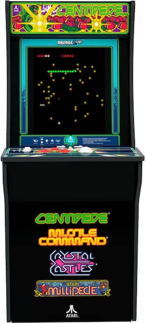
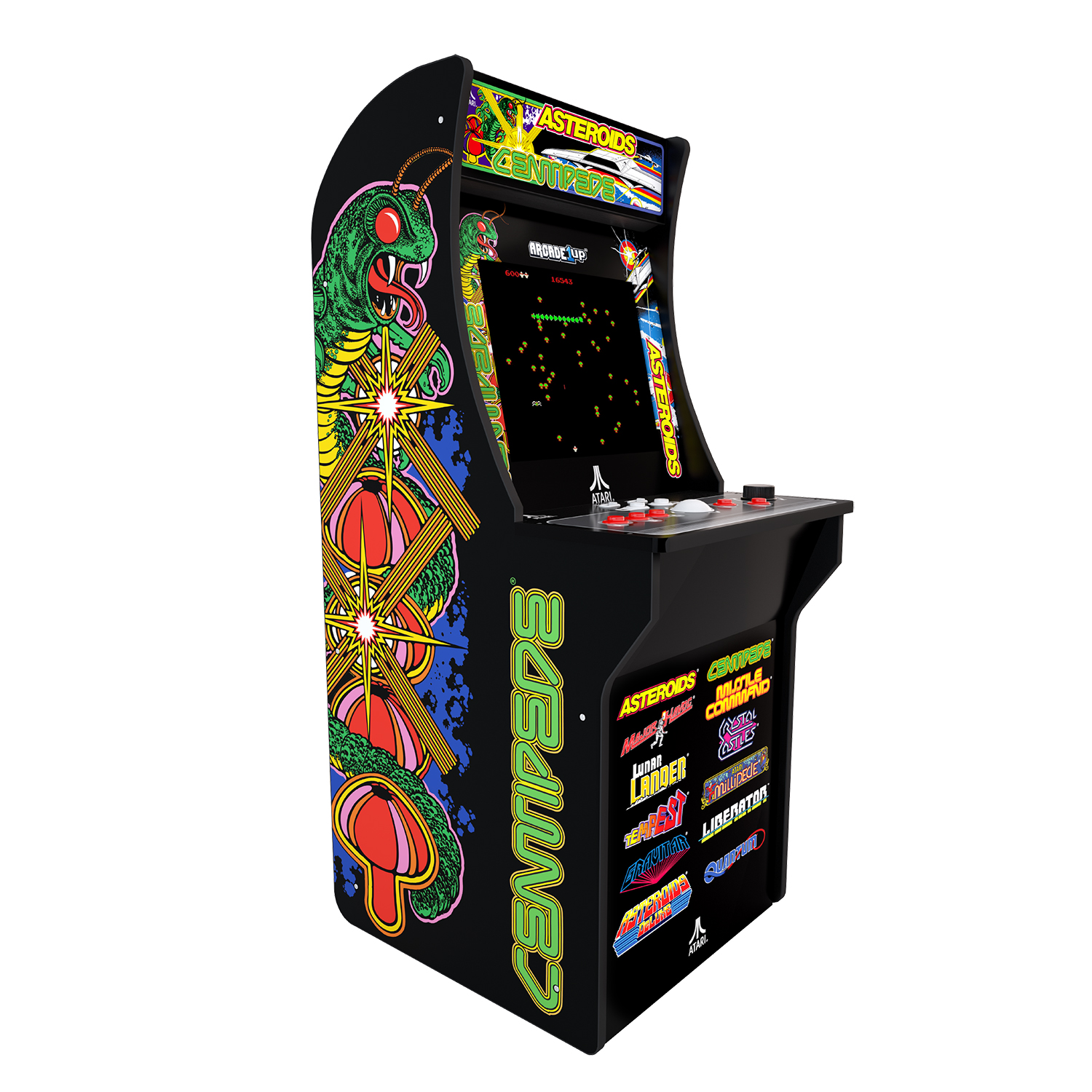
With this in mind, my main goal of modding this cabinet is to keep everything looking the same. Due to there really not being any trackballs on the market quite like the Arcade1Up's, I don't want to change it. So, my mod takes the default control panel(in which I did change the buttons to better quality) and connects it to a Pi.
I feel like the trackball by itself has a ton of games that you can play with even with just five buttons. ScummVM, Dosbox mouse games, tons of vertshooters play well with a trackball, etc... So, no drilling as well. I also wanted to use the on/off switch and the volume switch, which thanks another reddit user, was a cinch.
- A Raspberry Pi 3 w/ microsd card and power adapter
- A LCD Controller(I used this one)
- A USB TTL Adapter
- A 40 pin Breakout Board(I prefer w/ terminal block)
- Some Dupont Cables
I will not be going over how to set up your Pi. I'm using retropie w/ attract mode and am hardware rotating the screen because SCUMMVM and DOSBOX have no way to rotate that I know.
Hooking up the LCD Controller is best seen through ETA Primes original Pi Mod video. I don't feel like rehashing what he's already done beautifully.

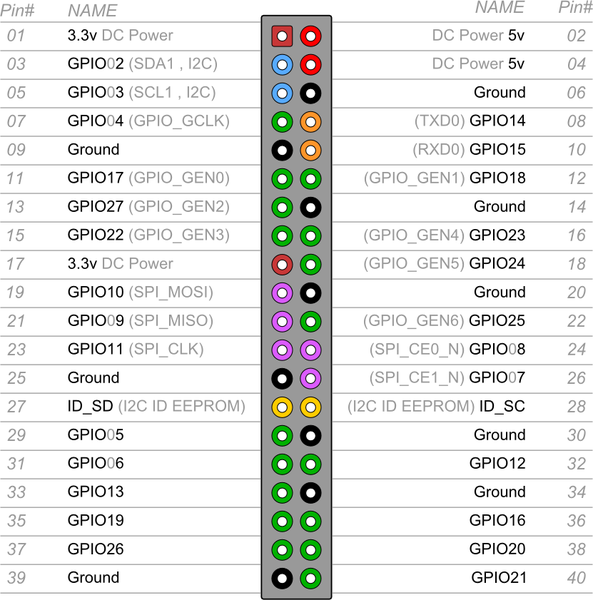
Ok, first step we gotta wire up our 40 pin. We're going to use the pinout guide by /u/BerryBerrySneaky on his megapost about modding. He's actually been really helpful throughout this whole process.
First we take those dupont female to female cables I linked earlier and we seperate them into individual cables. For Centipede you'll need 17 + 1 smaller wire. Now, we take the wires and on one end, we'll remove the female connector, so your wire should go from looking like the brown one to the green one. After that, strip away some of the cables insulation so that it looks like the blue cable in the image to the left. Do that for all 17 cables, so that one side has the connector and the other is bare.
| Pin | Connect to |
|---|---|
| 1 | P1 Start |
| 2 | Uart Pin 2 |
| 3 | P2 Start |
| 4 | Uart pin 1 |
| 5 | A Button |
| 6 | B Button |
| 7 | C Button |
| 13 | UART 5V |
| 14 | UART GND |
| 18 | Pi GND |
| 35 | Pwr Switch |
| 37 | Vol A(up) |
| 38 | Vol B(down) |
| 39 | Speaker |
| 40 | Speaker |

The next step is to add these wires to the breakout board. I chose a terminal block because it is very easy to attach and this one has numbers for each pin. If you unscrew the screw for a pin, the aperture underneath it will open, screwing it in closes it. All you have to do is put the bare wire in the aperture and close it on it. I like to attach note tabs to my wires and label them as I do this.
Attach a wire to every pin on the table above. Also, make a shorter wire with bare ends on both and attach it to both 36 and 32. 36 is the other end of the power switch and 32 is ground. Since we're hooking it up to the pi, I want to use the halt mechanism to turn my pi off and we need power to go to ground. With this we can easily hook up this to a USB controller or GPIO. I chose to use the PIs GPIO.
So, let's get connecting the buttons to the GPIO. Let's start with Ground. I had you connect ground to terminal 14, so let's hook it up to pin 39 on your Pi's GPIO. Make sure you connect it to the right place. If the Pi's USB ports are facing you, it's the bottom left pin. Next, Connect the power(terminal 35) to pin 5(GPIO3). I connected A to 29, B to 31, C to 33, P1 Start to 35, P2 Start to 37, Volume A to 38, and Volume B to 40. You can connect your buttons however you wish(I suggest just using the green ones), but if you don't want to edit my script, stick to what I did.

Now we need to hook up the trackballs interface. Make sure you remove the jumper on the TX and RX pins of your USB TTL Adapter.
Attach Terminal 4 to the TXD pin, Terminal 2 to the RXD pin, Terminal 14 to the GND pin right next to the RXD pin, and connect Terminal 13 to the 5V pin on it. After that connect the USB into your PI's usb. Now we should be able to read the trackball, but we're going to need a script for that, and that's the next section. Before that, we still have two wires on the terminal that haven't been connected to anything, let's fix that.
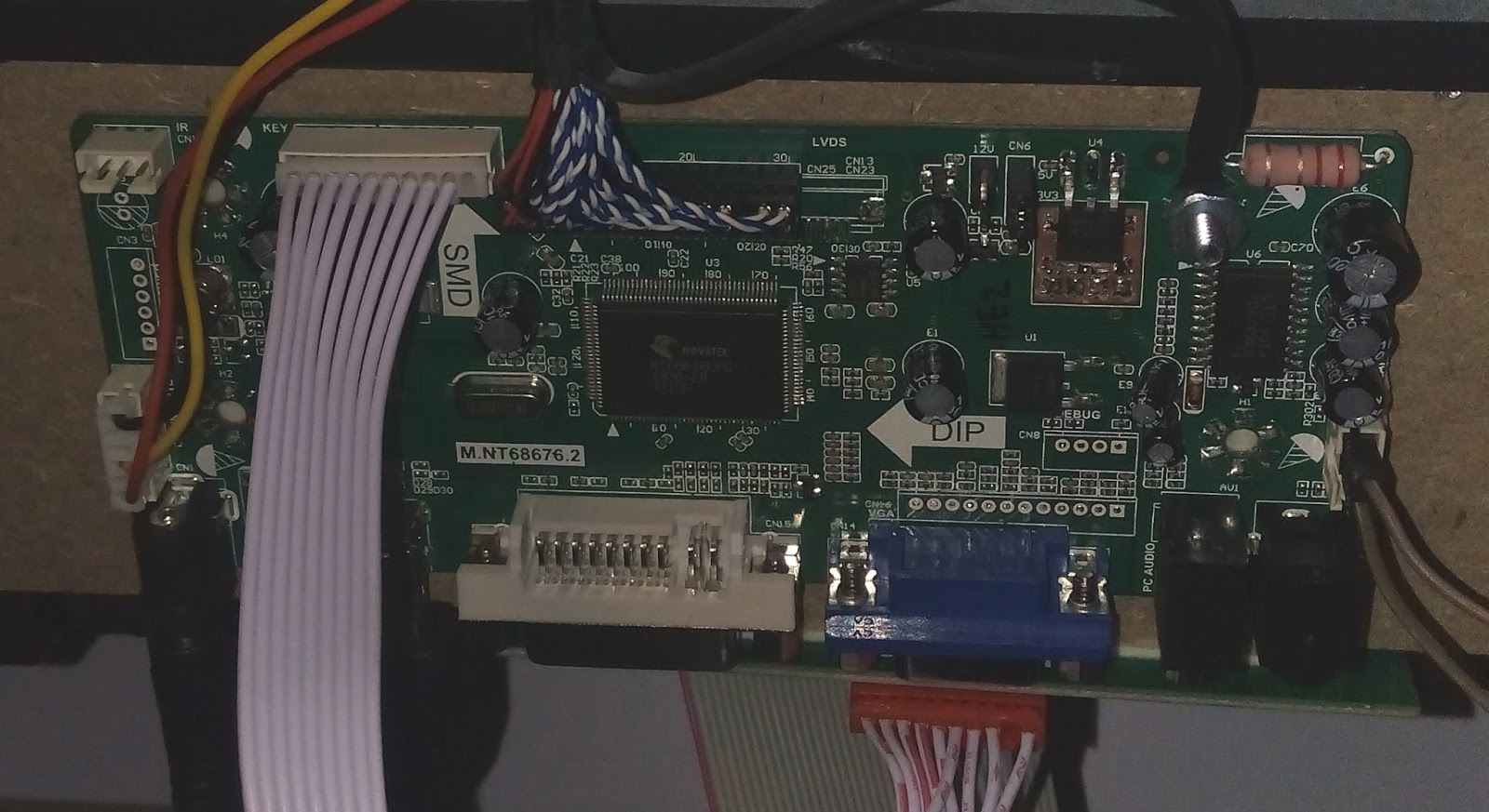
The two wires that are left are the speaker wires. If you got the same lcd controller board as me you can easily connect the speaker to it.
On the picture to the right is my LCD Board. Above the Audio outputs on the bottom right of the board is a 4 pin header. My brown wires are connected to the top two pins on this header. This is the left speaker and it puts out enough power to run our stock speaker!
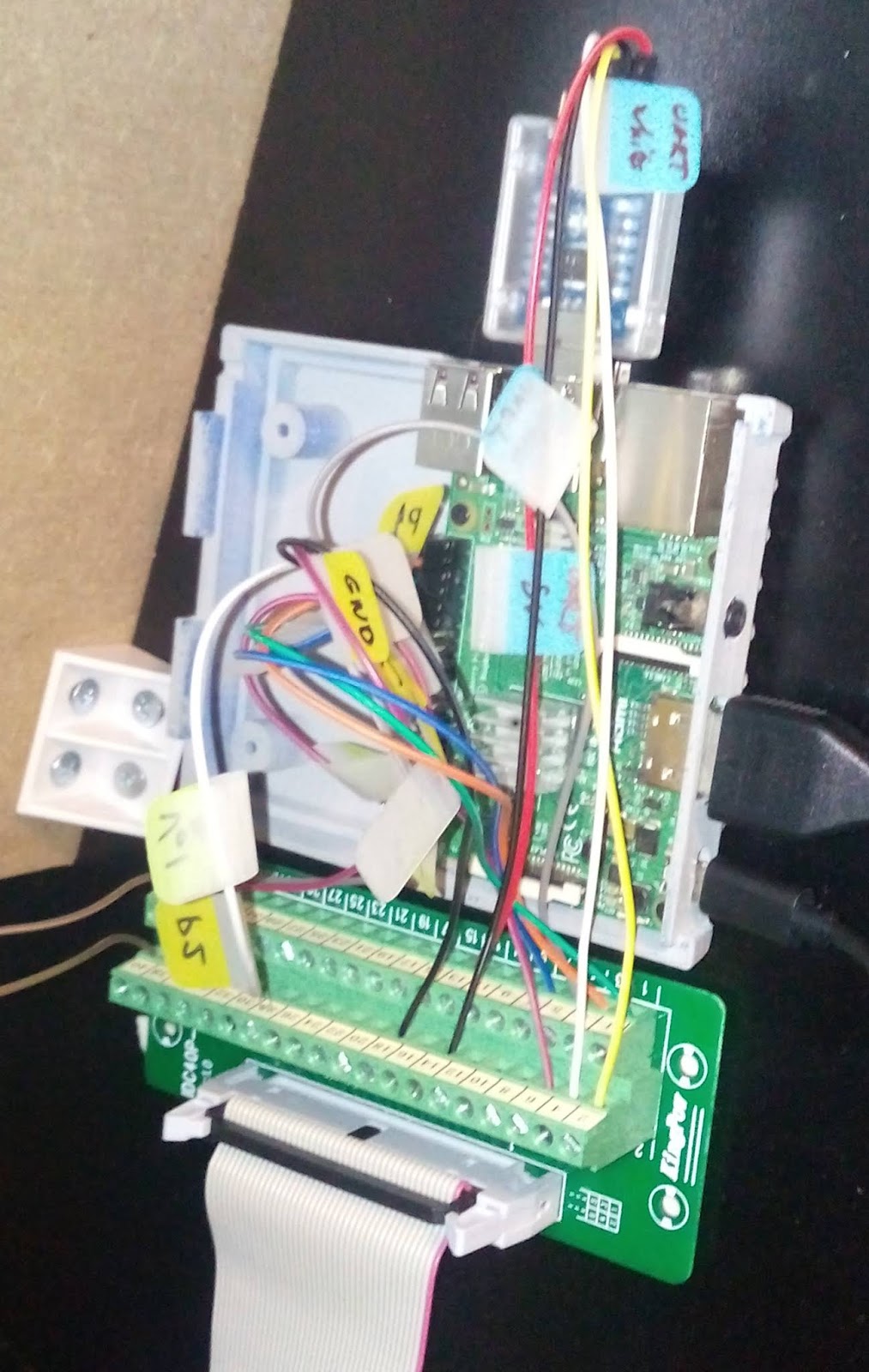
Once you got everything connected, it should look similar to my mess on the left. If you run your pi now, you'll notice, it doesn't detect any controller. Well, that's because we gotta code our own! Lucky for you, I got a python script you can start off of.
You'll need to install a few things before we get to my script, so my script requires:
- PySerial for the trackball
- GPIOZero For our buttons and volume switch
- pyAlsaAudio For Volume Control
- python-evdev to emulate a mouse and joystick
They are all fairly easy to install. I saved mine to /home/pi as pyTrackball.py. To get this to run at startup edit your /etc/rc.local and add the line:
python /home/pi/pyTrackball.py &
There are two more edits we need to make before the interface works as well as it can. First, we gotta get the pi to downmix the audio to mono. The easiest way is to just follow this guide. Finally, we need to halt the pi, with the power switch mod. It's best to look at /u/icculus's guide for that on his website.
Now that you've down all that, the entire stock arcade control panel should be completely interfaced with your pi. The only really kicker to note is that I implemented both a joystick mode and mouse mode in the python script. To swap between them you just need to hold P2 Start and press A.
My script can easily be adapted for other models of the cabinet. If you follow the pinouts on /u/BerryBerrySneaky's post, and add in the extra buttons in a similar fashion to how I did the buttons on the centipede model, then the atari 12 in 1 can easily be adapted to use it. I already have code in for the spinner, even though my unit does not have one. The asteroids cabinet as well can easily be used with similar modifications
Finally, I would still suggest people use the 40 pin terminal method as I feel it ends up looking cleaner all over. If you aren't adding buttons, it's a great option. Heck, when the Mortal Kombat unit comes out, I'm going to use the terminal breakout with 2 usb controllers and gpio:)
I plan on improving my script in the future. I currently want to implement it with the autostart.sh scripts and have it change modes based on game I'm running(adding an accelerated mouse mode for SCUMMVM and DOSBOX). After getting all that, I'll probably change it to C and compile it since interpreted languages take a performance hit.
I also want to get my serial settings a bit better. I still have dropped bytes with my current settings with tons of trackball movement. Thanks to /u/BerryBerrySneaky's suggestion that it was 7N1 not 8N1, the script has performed much better, but the problem still arises. Right now I just drop the buffer if I desync like that, but I feel I need to resynchronize better if this remains an issue.
Right now, I'm just having fun playing Shmups with a trackball and some Trackball games I've never played. Hope this helps some people out there. The Street Fighter cabinets aren't the only ones worth modding, Centipede works just as well!