-
Notifications
You must be signed in to change notification settings - Fork 0
/
Copy pathlora_e5.md.bak
589 lines (381 loc) · 24.3 KB
/
lora_e5.md.bak
1
2
3
4
5
6
7
8
9
10
11
12
13
14
15
16
17
18
19
20
21
22
23
24
25
26
27
28
29
30
31
32
33
34
35
36
37
38
39
40
41
42
43
44
45
46
47
48
49
50
51
52
53
54
55
56
57
58
59
60
61
62
63
64
65
66
67
68
69
70
71
72
73
74
75
76
77
78
79
80
81
82
83
84
85
86
87
88
89
90
91
92
93
94
95
96
97
98
99
100
101
102
103
104
105
106
107
108
109
110
111
112
113
114
115
116
117
118
119
120
121
122
123
124
125
126
127
128
129
130
131
132
133
134
135
136
137
138
139
140
141
142
143
144
145
146
147
148
149
150
151
152
153
154
155
156
157
158
159
160
161
162
163
164
165
166
167
168
169
170
171
172
173
174
175
176
177
178
179
180
181
182
183
184
185
186
187
188
189
190
191
192
193
194
195
196
197
198
199
200
201
202
203
204
205
206
207
208
209
210
211
212
213
214
215
216
217
218
219
220
221
222
223
224
225
226
227
228
229
230
231
232
233
234
235
236
237
238
239
240
241
242
243
244
245
246
247
248
249
250
251
252
253
254
255
256
257
258
259
260
261
262
263
264
265
266
267
268
269
270
271
272
273
274
275
276
277
278
279
280
281
282
283
284
285
286
287
288
289
290
291
292
293
294
295
296
297
298
299
300
301
302
303
304
305
306
307
308
309
310
311
312
313
314
315
316
317
318
319
320
321
322
323
324
325
326
327
328
329
330
331
332
333
334
335
336
337
338
339
340
341
342
343
344
345
346
347
348
349
350
351
352
353
354
355
356
357
358
359
360
361
362
363
364
365
366
367
368
369
370
371
372
373
374
375
376
377
378
379
380
381
382
383
384
385
386
387
388
389
390
391
392
393
394
395
396
397
398
399
400
401
402
403
404
405
406
407
408
409
410
411
412
413
414
415
416
417
418
419
420
421
422
423
424
425
426
427
428
429
430
431
432
433
434
435
436
437
438
439
440
441
442
443
444
445
446
447
448
449
450
451
452
453
454
455
456
457
458
459
460
461
462
463
464
465
466
467
468
469
470
471
472
473
474
475
476
477
478
479
480
481
482
483
484
485
486
487
488
489
490
491
492
493
494
495
496
497
498
499
500
501
502
503
504
505
506
507
508
509
510
511
512
513
514
515
516
517
518
519
520
521
522
523
524
525
526
527
528
529
530
531
532
533
534
535
536
537
538
539
540
541
542
543
544
545
546
547
548
549
550
551
552
553
554
555
556
557
558
559
560
561
562
563
564
565
566
567
568
569
570
571
572
573
574
575
576
577
578
579
580
581
582
583
584
585
586
587
588
589
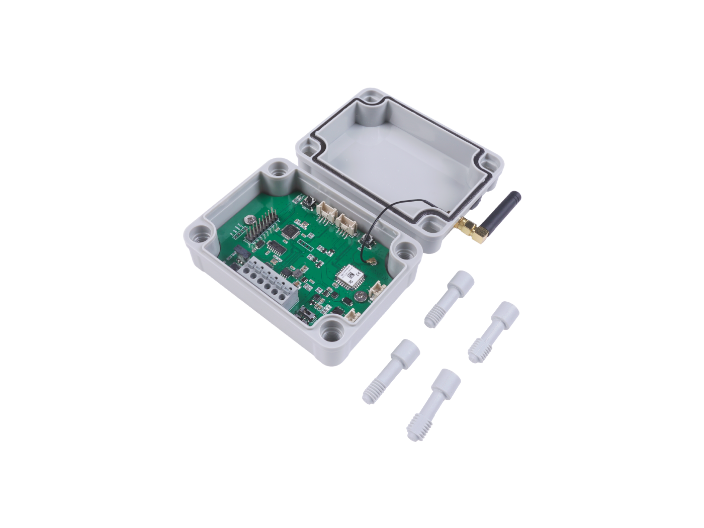
LoRa-E5 CAN FD Development Kit is a compact development toolset for you to unlock the powerful performance of the [LoRa-E5 STM32WLE5JC](https://www.seeedstudio.com/LoRa-E5-Wireless-Module-p-4745.html) as well as CAN FD and RS485 communication. We also provide a simple waterproof case and solar charging interface, you can easily make a sensor node placed outdoors.
LoRa-E5 Dev Board embedded with LoRa-E5 STM32WLE5JC Module that supports LoRaWAN protocol on global frequency band. It leads out full GPIOs of LoRa-E5 supporting various data protocols and interfaces including RS-485, Grove, male/female headers, etc. It would be a perfect choice for fast testing and rapid prototyping of your LoRa IoT projects.
LoRa-E5 Dev Board embedded with LoRa-E5 STM32WLE5JC Module, which is the world-first combo of LoRa RF and MCU chip into one single tiny chip and is FCC and CE certified. It is powered by ARM Cortex-M4 core and Semtech SX126X LoRa chip, supports both LoRaWAN and LoRa protocol on the worldwide frequency and (G)FSK, BPSK, (G)MSK, and LoRa modulations.
Learn more about [LoRa-E5](https://wiki.seeedstudio.com/LoRa-E5_STM32WLE5JC_Module/) here.
LoRa-E5 Dev Board has a long-distance transmission range of LoRa-E5 up to 10km in an open area. The sleep current of LoRa-E5 modules on board is as low as 2.1 uA(WOR mode). It is designed with industrial standards with a wide working temperature at -40 ℃ ~ 85℃, high sensitivity between -116.5 dBm ~ -136 dBm, and power output up to +20.8dBm at 3.3V.
LoRa-E5 Dev Board also has rich interfaces. Developed to unlock the full functionality of the LoRa-E5 module, LoRa-E5 Dev Board has led out full 28 pins of LoRa-E5 and provides with rich interfaces including Grove connectors, RS-485 terminal, male/female pin headers for you to connect sensors and modules with different connectors and data protocols, saving your time on wire soldering. You could also easily power the board by connecting the battery holder with 2 AA batteries, enabling temporary use when lacking an external power source. It is a user-friendly board for easy testing and rapid prototyping.
Since LoRa-E5 is a LoRaWAN chip with an MCU, there are three main ways to utilize the LoRa-E5 Dev Board:
1: Connect LoRa-E5 Dev Board to PC via USB and control by AT commands
There is a built-in USB to UART function on board, you could just simply connect the LoRa-E5 Dev Board to your PC with a USB type C cable, and use serial communication software to send AT commands and read data from the board
2: Connect LoRa-E5 Dev Board to another mainboard via UART and control by AT commands
For example, connect LoRa-E5 Dev Board to Seeeduino XIAO and the Expansion Board via UART, and send AT commands and read data from Seeeduino XIAO through Arduino IDE serial monitor.
3: Develop user application by using SDK
Develop your own LoRa development board with MCU function by using STM32Cube Programmer, which is the SDK officially provided by STMicroelectronics. To download this SDK resource, please find the resources in learning and document down below.
With all the outstanding features listed above, the LoRa-E5 Dev Board will be a superior choice for IoT device development, testing, prototyping, and applications in long-distance, ultra-low power consumption IoT scenarios like smart agriculture, smart office, and smart industry.
If you are unfamiliar with LoRa and LoRaWAN technology, please check out this blog [LoRapedia](https://www.seeedstudio.com/blog/2020/08/03/lorapedia-an-introduction-of-lora-and-lorawan-technology/) in detail.
## **FEATURES**
-----------
* Ultra-low power consumption and high performance
* Easy testing and rapid prototyping
* CAN FD communication
* RS485 Interface
* Global LoRaWAN and loRa frequency plan supported
* Long-distance transmission range to 10km(ideal value in open area)
## **PART LIST**
--------------------
* LoRa-E5 CAN FD Development board
* Antenna (EU868/US915)
* Waterproof case
## **HARWARE OVERVIEW**
----------------------
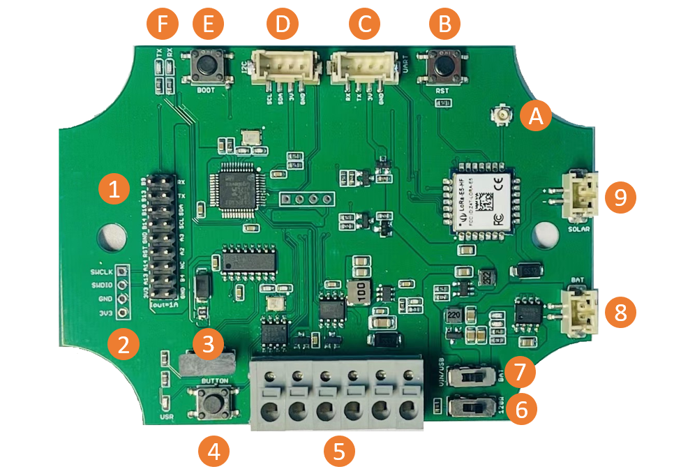
1 - 2x9 Header
2 - SWD Interface
3 - Type-C USB connnector
4 - User button - Connected to PB3
5 - CAN&485&Power Input connector
6 - 120Ω Switch for CAN Bus
7 - Power switch
8 - 3.7V Lipo battery
9 - Solar Input, 4.5~6V
A - Antenna
B - Reset button
C/D - Grove connector for UART and I2C
E - Boot button
F - Led indicators for CAN Bus
## **SPECIFICATION**
------------
|Item|Specifications|
|----|--------------|
|Voltage supply|5V/USB, 3.7V Lipo Battery, 4.5~28V DC input|
|Voltage output|3.3V|
|Power output|Up to 20.8dBm at 3.3V|
|Frequency|EU868 / US915 / AU915 / AS923 / KR920 / IN865|
|Protocol|LoRaWAN|
|Sensitivity|116.5dBm ~ -136dBm|
|Modulation|LoRa, (G)FSK, (G)MSK, BPSK|
|CAN 2.0 speed|Up to 1Mb/s|
|CAN FD speed|Up to 5Mb/s|
## **APPLICATION**
---------------
* A common Lora usage scenario, that is, building a Lora sensor network. A large number of sensors in the industry are transmitted through CAN Bus. With the Lora-E5 CAN Bus Dev board you can use the on-board CAN Bus function to read the sensors, and send the data through Lora.
* Since the circuit board can receive 5-28V input, the user can connect the circuit board to the OBD interface, get the data of the car and send it out through Lora
### ***Application Notes***
**1. Factroy AT Firmare**
LoRa-E5 series has a built-in AT command firmware, which supports LoRaWAN Class A/B/C protocol and a wide frequency plan: EU868/US915/AU915/AS923/KR920/IN865. With this AT command firmware, developers can easily and quickly build their prototype or application.
The AT command firmware contains a bootloader for DFU and the AT application. The "PB13/SPI_SCK/BOOT" pin is used to control LoRa-E5 to stay in the bootloader or jump to the AT application. When PB13 is HIGH, the module will jump to AT application after reset, with a default baud rate of 9600. When PB13 is LOW (press the "Boot" button on LoRa-E5 Dev Board or LoRa-E5 mini), the module will stay in the bootloader, and keep transmitting "C" character every 1S at baud rate 115200.
!!!Attention
- Factory AT Firmware is programmed with RDP(Read Protection) Level 1, developers need to remove RDP first with STM32Cube Programmer. Note that regression RDP to level 0 will cause a flash memory mass to erase and the Factory AT Firmware can't be restored again.
- The "PB13/SPI_SCK/BOOT" pin on the LoRa-E5 module is just a normal GPIO, not the "BOOT0" pin of the MCU. This "PB13/SPI_SCK/BOOT" pin is used in the bootloader of the Factory AT firmware, to decide to jump to APP or stay in bootloader(for DFU). The real "BOOT0" pin doesn't pinout to the module, so users need to be careful when developing the low-power applications.
**2. Clock Configuration**
2.1 HSE
- 32MHz TCXO
- TCXO power supply: PB0-VDD_TCXO
2.2 LSE
- 32.768KHz crystal oscillator
**3. RF Switch**
**LoRa-E5 module ONLY transmits through RFO_HP:**
- Receive: PA4=1, PA5=0
- Transmit(high output power, SMPS mode): PA4=0, PA5=1
## **GETTING STARTED**
----------------
### ***1. Quick start of AT Commands***
#### 1.1 Preparation
- **Step 0.** Install [the driver for CH340G](https://sparks.gogo.co.nz/ch340.html)
- **Step 1.** Connect LoRa-E5 Development Board to PC via a Type-C cable
- **Step 2.** Open a serial tool(eg. Arudino Serial Monitor), select the right COM port, set baudrate to 9600 and select Both NL & CR
- **Step 3.** Try to send "AT" and you will see the response.

#### ***1.2 Basic AT Commands***
- AT+ID // Read all, DevAddr(ABP), DevEui(OTAA), AppEui(OTAA)
- AT+ID=DevAddr // Read DevAddr
- AT+ID=DevEui // Read DevEui
- AT+ID=AppEui // Read AppEui
- AT+ID=DevAddr,"devaddr" // Set new DevAddr
- AT+ID=DevEui,"deveui" // Set new DevEui
- AT+ID=AppEui,"appeui" // Set new AppEui
- AT+KEY=APPKEY,"16 bytes length key" // Change application session key
- AT+DR=band // Change the Band Plans
- AT+DR=SCHEME // Check current band
- AT+CH=NUM, 0-7 // Enable channel 0~7
- AT+MODE="mode" // Select work mode: LWOTAA, LWABP or TEST
- AT+JOIN // Send JOIN request
- AT+MSG="Data to send" // Use to send string format frame which is no need to be confirmed by the server
- AT+CMSG="Data to send" // Use to send string format frame which must be confirmed by the server
- AT+MSGHEX="xx xx xx xx" // Use to send hex format frame which is no need to be confirmed by the server
- AT+CMSGHEX="xx xx xx xx" // Use to send hex format frame which must be confirmed by the server
#### 1.3 Connect and send Data to TTN
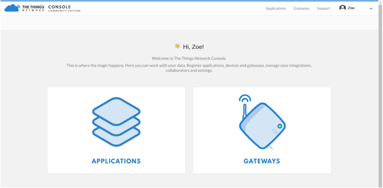
- Step 1: Load into TTN website: https://www.thethingsnetwork.org and create your account, then access "Console" and first click on "APPLICATIONS"
- Step 2: Add an Application

- Step3: Copy the `APPLICATION EUIS` and click "register device" button to add your device to TTN

- Step4: Send AT command `AT+ID=DevEu`i to get your Device EUI, send AT command `AT+KEY=APPKEY,"11223344556677889900112233445566"` to set the App Key, and send AT command `AT+ID=AppEui,"APPLICATION EUIS you copy just now"` to set the App EUI, finally fill all these EUIs and Key to the page to register your device
```
Tx: AT+ID=DevEui
Rx: +ID: DevEui, 2C:F7:F1:20:24:90:16:1D
Tx: AT+KEY=APPKEY,"11223344556677889900112233445566"
Rx: +KEY: APPKEY 11223344556677889900112233445566
Tx: AT+ID=AppEui,"70B3D57ED003F06A"
Rx: +ID: AppEui, 70:B3:D5:7E:D0:03:F0:6A
```

- Step 5: Register your LoRaWAN Gateway on TTN Console,
please refer to the instruction shown in [The Things Indoor Gateway wiki page: The Things Indoor Gateway Get Started with SenseCAP](https://wiki.seeedstudio.com/The-Things-Indoor-Gateway/#step-2-gateway-registration-on-ttn-console)
- Step 6: Type the following AT Commmand to connect to TTN
```
Tx: AT+ID
Rx: +ID: DevAddr, 24:90:16:1D
+ID: DevEui, 2C:F7:F1:20:24:90:16:1D
+ID: AppEui, 70:B3:D5:7E:D0:03:F0:6A
Tx: AT+DR=EU868
Rx: +DR: EU868
Tx: AT+CH=NUM,0-2
Rx: +CH: NUM, 0-2
// If you are using US915 FSB2
// Tx: AT+DR=US915
// Rx: +DR: US915
// Tx: AT+CH=NUM,8-15
// Rx: +CH: NUM, 8-15
Tx: AT+MODE=LWOTAA
Rx: +MODE: LWOTAA
Tx: AT+JOIN
Rx: +JOIN: Start
+JOIN: NORMAL
+JOIN: Network joined
+JOIN: NetID 000013 DevAddr 26:01:5F:66
+JOIN: Done
```
If you see `+JOIN: Network joined` in your serial console, congratulations, your device have already connect to TTN! You can also check your device status at the "overview" page.

- Step 7: Type the following AT Command to send data to TTN
```
// send string "HELLO" to TTN
Tx: AT+MSG=HELLO
Rx: +MSG: Start
+MSG: FPENDING
+MSG: RXWIN2, RSSI -112, SNR -1.0
+MSG: Done
// send hex "00 11 22 33 44"
Tx: AT+MSGHEX="00 11 22 33 44"
Rx: +MSGHEX: Start
+MSGHEX: Done
```

- Step 8: For more information about AT Commands, please refer to [LoRa-E5 AT Command Specification](https://files.seeedstudio.com/products/317990687/res/LoRa-E5%20AT%20Command%20Specification_V1.0%20.pdf)
### ***2. Develop with STM32Cube MCU Package***
This section is for LoRa-E5 Mini or LoRa-E5 Dev Board, aiming at creating a LoRaWAN End Node with STM32Cube MCU Package for STM32WL series(SDK), to join and send data to LoRaWAN Network.
!!!Attention
Please read [Erase Factory AT Firmware](https://wiki.seeedstudio.com/LoRa_E5_mini/#21-erase-factory-at-firmware) section first, as if we need to erase the Factory AT Firmware before we program with SDK. After erasing the Factory AT Firmware it CANNOT be recovered.
#### 2.1 Preparations
Softwares:
- Install [STM32CubeIDE(to compilation and debug)](https://my.st.com/content/my_st_com/en/products/development-tools/software-development-tools/stm32-software-development-tools/stm32-ides/stm32cubeide.html)
- Install [STM32CubeProgrammer(to program STM32 devices)](https://my.st.com/content/my_st_com/en/products/development-tools/software-development-tools/stm32-software-development-tools/stm32-programmers/stm32cubeprog.license=1614563305396.product=STM32CubePrg-W64.version=2.6.0.html)
- Download and extract [STM32Cube MCU Package for STM32WL series(SDK)](https://my.st.com/content/my_st_com/en/products/embedded-software/mcu-mpu-embedded-software/stm32-embedded-software/stm32cube-mcu-mpu-packages/stm32cubewl.license=1608693595598.product=STM32CubeWL.version=1.0.0.html#overview)
Hardwares:
- LoRaWAN Gateway connected to LoRaWAN Network Server(e.g. TTN)
- ST-Link connect to the SWD interface.
#### 2.2 GPIO Configuration Overview
- As the hardware design of LoRa-E5 series is a bit different with NUCLEO-WL55JC, the official STM32WL55JC development board from ST, developers need to reconfigure some gpios, to adapt the SDK example to LoRa-E5 series. We have already reconfigured gpios in this example, but we think it is nessary to point out the difference.
|SDK Example Label|GPIO of NUCLEO-WL55JC|GPIO of LoRa-E5|
|---------|---------------------|------------------------------------------|
|RF_CTRL1|PC4|PA4|
|RF_CTRL2|PC5|PA5|
|RF_CTRL3|PC3|None|
|BUT1|PA0|PB13 (Boot Button)|
|BUT2|PA1|None|
|BUT3|PC6|None|
|LED1|PB15|None|
|LED2|PB9|PB5|
|LED3|PB11|None|
|DBG1|PB12|PA0 (D0 Button)|
|DBG2|PB13|PB10|
|DBG3|PB14|PB3|
|DBG4|PB10|PB4|
|Usart|Usart2(PA2/PA3)|Usart1(PB6/PB7)|
#### 2.3 Build the LoRaWAN End Node Example
- Download and copy [this repo](https://github.com/seeed-lora/LoRa-E5-LoRaWAN-End-Node.git) to your SDK folder `en.stm32cubewl\STM32Cube_FW_WL_V1.0.0\Projects\NUCLEO-WL55JC\Applications\LoRaWAN` and replace the origin `en.stm32cubewl\STM32Cube_FW_WL_V1.0.0\Projects\NUCLEO-WL55JC\Applications\LoRaWAN\LoRaWAN_End_Node` folder
- Open the `LoRaWAN_End_Node` example with `STM32CubeIDE`, by double click file `LoRaWAN_End_Node\STM32CubeIDE\.project`
- Click `Build Debug` for this example, it should work without any errors

#### 2.4 Modify your Device EUI, Application EUI, Application KEY and your LoRawan Region
- Please follow the [guide](https://wiki.seeedstudio.com/LoRa_E5_mini/#13-connect-and-send-data-to-ttn) here to setup your TTN application, get your Application EUI and copy it to the macro definition `LORAWAN_JOIN_EUI` in `LoRaWAN/App/se-identity.h` , for example, my Application EUI is `70 B3 D5 7E D0 03 F0 6A` :
```C
// LoRaWAN/App/se-identity.h
/*!
* App/Join server IEEE EUI (big endian)
*/
#define LORAWAN_JOIN_EUI { 0x70, 0xB3, 0xD5, 0x7E, 0xD0, 0x03, 0xF0, 0x6A }
```
- Also, you can modify your Device EUI and Application Key, by setting the macro definition `LORAWAN_DEVICE_EUI` and `LORAWAN_NWK_KEY` in `LoRaWAN/App/se-identity.h` , don't forget to ensure `LORAWAN_DEVICE_EUI` and `LORAWAN_NWK_KEY` are the same as the `Device EUI` and `App Key` in TTN console.
```C
// LoRaWAN/App/se-identity.h
/*!
* end-device IEEE EUI (big endian)
*/
#define LORAWAN_DEVICE_EUI { 0x00, 0x80, 0xE1, 0x15, 0x00, 0x07, 0x4C, 0xD5 }
/*!
* Network root key
*/
#define LORAWAN_NWK_KEY 2B,7E,15,16,28,AE,D2,A6,AB,F7,15,88,09,CF,4F,3C
```

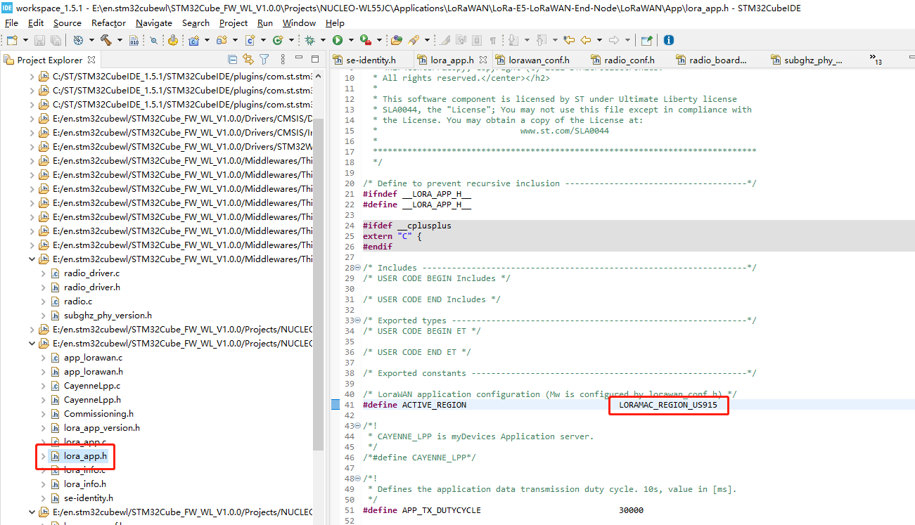
- The default LoRaWAN Region is `EU868`, you can modify it, by setting the macro definition `ACTIVE_REGION` in `LoRaWAN/App/lora_app.h`
```c
// LoRaWAN/App/lora_app.h
/* LoraWAN application configuration (Mw is configured by lorawan_conf.h) */
/* Available: LORAMAC_REGION_AS923, LORAMAC_REGION_AU915, LORAMAC_REGION_EU868, LORAMAC_REGION_KR920, LORAMAC_REGION_IN865, LORAMAC_REGION_US915, LORAMAC_REGION_RU864 */
#define ACTIVE_REGION LORAMAC_REGION_EU868
```
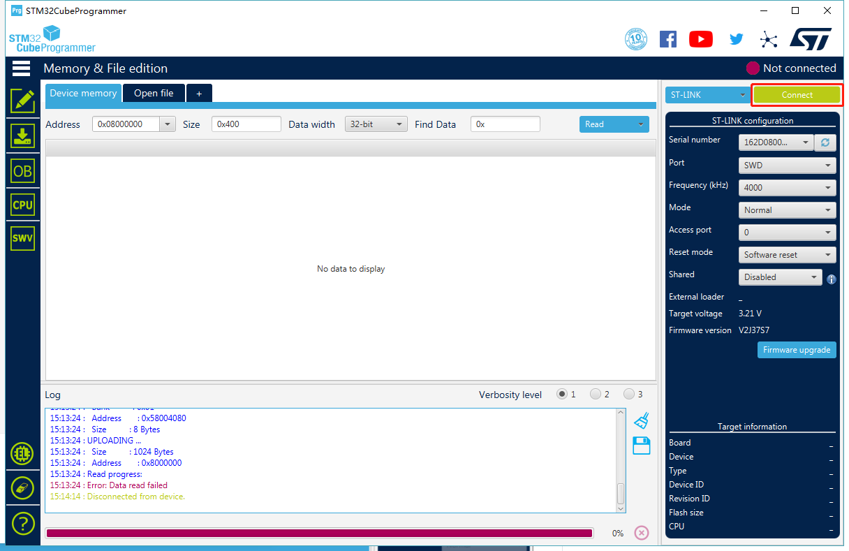
- After modification, please **rebuild the example** and program to your LoRa-E5. Open `STM32CubeProgrammer`, connect ST-LINK to your PC, hold `RESET Button` of your Device, then click `Connect` and release `RESET Button`:
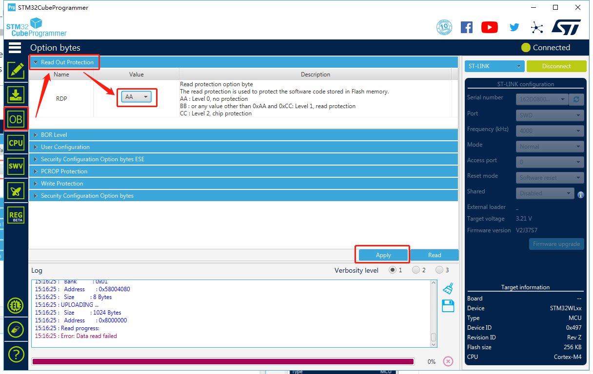
- Make sure the Read Out Protection is `AA`, if it is shown as `BB`, select `AA` and click `Apply`:
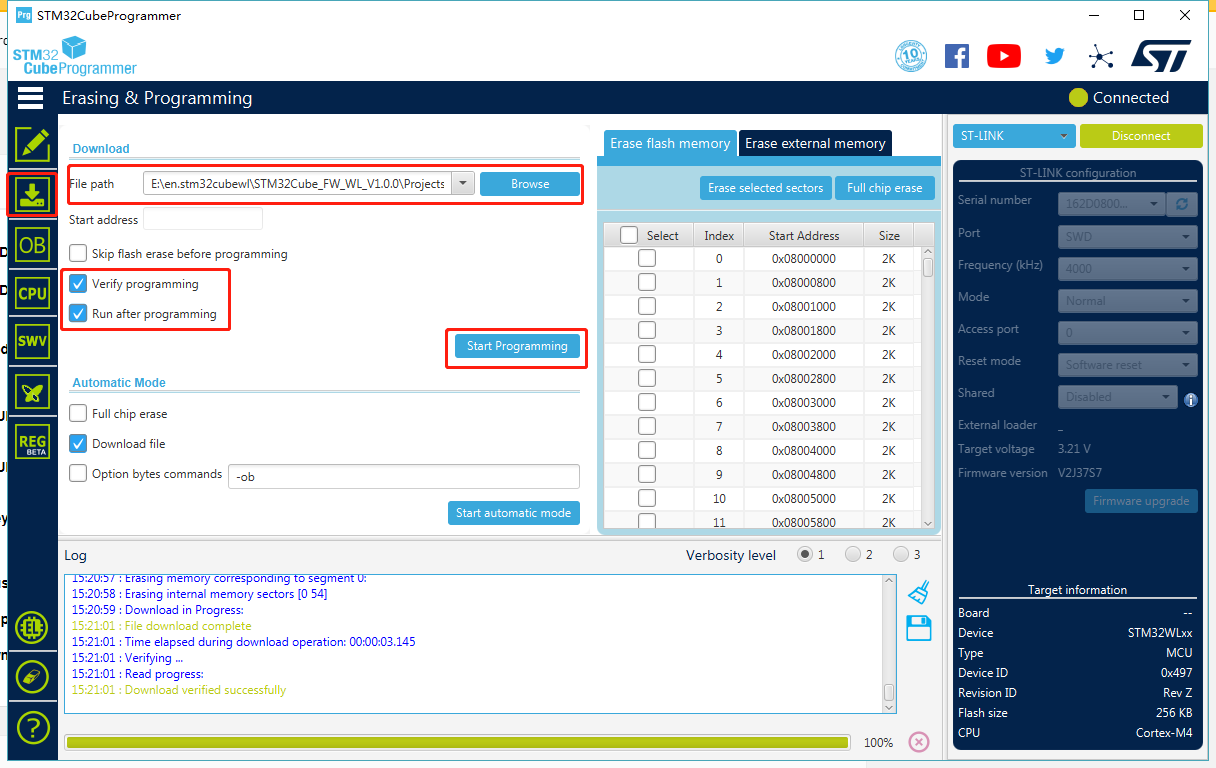
- Now, go to the `Erasing & Programming` page, select your hex file path(my path is `E:\en.stm32cubewl\STM32Cube_FW_WL_V1.0.0\Projects\NUCLEO-WL55JC\Applications\LoRaWAN\LoRaWAN_End_Node\STM32CubeIDE\LoRaWAN_End_Node_Debug.hex` ), select the programming options as the following picture, then click `Start Programming`! Once the prgramming is finished,
#### 2.5 Connect to TTN
- If your LoRaWAN Gateway and TTN are setup, LoRa-E5 will join successfully after reset! A comfirm LoRaWAN package will be sent to TTN every 30 seconds. The following log will come out from the serial port if the join is successful:
```
APP_VERSION: V1.0.0
MW_LORAWAN_VERSION: V2.2.1
MW_RADIO_VERSION: V0.6.1
###### OTAA ######
###### AppKey: 2B 7E 15 16 28 AE D2 A6 AB F7 15 88 09 CF 4F 3C
###### NwkKey: 2B 7E 15 16 28 AE D2 A6 AB F7 15 88 09 CF 4F 3C
###### ABP ######
###### AppSKey: 2B 7E 15 16 28 AE D2 A6 AB F7 15 88 09 CF 4F 3C
###### NwkSKey: 2B 7E 15 16 28 AE D2 A6 AB F7 15 88 09 CF 4F 3C
###### DevEui: 00-80-E1-15-00-07-4C-D5
###### AppEui: 70-B3-D5-7E-D0-03-F0-6A
0s045:TX on freq 868100000 Hz at DR 0
1s550:MAC txDone
6s572:RX_1 on freq 868100000 Hz at DR 0
6s779:MAC rxTimeOut
7s572:RX_2 on freq 869525000 Hz at DR 0
7s709:PRE OK
8s246:HDR OK
9s393:MAC rxDone
###### = JOINED = OTAA =====================
30s068:temp= 25
30s068:VDDA= 254
30s069:TX on freq 868500000 Hz at DR 0
30s082:SEND REQUEST
31s728:MAC txDone
32s750:RX_1 on freq 868500000 Hz at DR 0
32s957:MAC rxTimeOut
33s706:RX_2 on freq 869525000 Hz at DR 3
33s744:PRE OK
33s815:HDR OK
33s897:MAC rxDone
###### ========== MCPS-Confirm =============
```

- Cheers! You have already connected LoRa-E5 to LoRaWAN Network! Can't wait to see you develop some wonderful LoRaWAN End Node applications!
## **POWER MANAGEMENT**
--------------
The system can be powered in 3 ways.
* Type C USB
* 3.7V lipo battery
* 4.5~28VDC via the Terminal
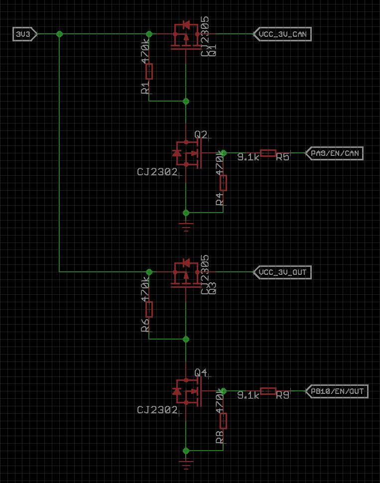
To save power, the system has two 3.3V branches, controlled by MOSFETs.
* 3.3V power supply for CAN and 485
* Grove 3.3V output
The schematics shown as below,
## **CAN FD Usage**
---------------
LoRa E5 CAN FD dev board supports CAN FD and CAN 2.0 communication protocols. We use a microcontroller GD32C103 with CAN FD function as CAN controller, we have written a firmware for GD32C103, through this firmware, CAN FD bus can be read and written through I2C. The rate of the I2C bus is 100kb/s.
### ***Features of CAN Bus***
* I2C Address: 0x41
* Rate of I2C: 100kb/s
* Max baudrate of CAN FD: 5Mb/s
### ***Register Address***
|ADDRESS|DESCRIBE|
|-------|--------|
|0x09|CAN Setting|
|0x05|Send a Frame|
|0x04|Check if CAN Bus receive a frame|
|0x06|Read the basic info of a can frame|
|0x07|Read first 32 bytes of a can frame|
|0x08|Read nex 32 bytes of a can frame (if have)|
### ***Configuring CAN FD***
Before we can start using CAN FD, we need to send 49 data passes to the CAN FD controller.
These data are defined as follows
|BYTE|DESCRIBE|
|---|---------|
|0|Register address, 0x09|
|1-4|CAN2.0 baud rate, 4 bytes, preceded by high-order 8 bits|
|5-8|CANFD baud rate, 4 bytes, preceded by high-order 8 bits|
|9|Mask&Filt0 flag, 0: No set, 1: Set|
|10|Extended frame flag for Mask&Filt0, 1 for extended frame, 0 for standard frame|
|11-14|Mask0, 4 bytes|
|15-18|Filt0, 4 bytes|
|19|Mask&Filt0 flag, 0: No set, 1: Set|
|20|Extended frame flag for Mask&Filt0, 1 for extended frame, 0 for standard frame|
|21-24|Mask0, 4 bytes|
|25-28|Filt0, 4 bytes|
|29|Mask&Filt0 flag, 0: No set, 1: Set|
|30|Extended frame flag for Mask&Filt0, 1 for extended frame, 0 for standard frame|
|31-34|Mask0, 4 bytes|
|35-38|Filt0, 4 bytes|
|39|Mask&Filt0 flag, 0: No set, 1: Set|
|40|Extended frame flag for Mask&Filt0, 1 for extended frame, 0 for standard frame|
|41-44|Mask0, 4 bytes|
|45-48|Filt0, 4 bytes|
### ***Send a CAN Frame***
|BYTE|DESCRIBE|
|----|--------|
|0|Register address, 0x05|
|1-4| ID for CAN frame|
|5|Remote frame flag, 1 for remote frame, 0 for data frame|
|6|Ext or standard frame, 1 for ext frame, 0 for std frame|
|7|CAN FD flag, 1 for CAN FD frame, 0 for std frame|
|8|Length of data frame|
|9-n|Data|
### ***Read a CAN Frame***
Before reading CAN Bus data, we need to see if CAN Bus has received data.
We can read register 0x04 to check the number of data received by CAN Bus. If the returned number is not 0, it means that CAN Bus has received data.
First, we need to read 8 Bytes of data from register 0x06, which is the basic content of a CAN Frame. The definitions of these 8 data are as follows.
|BYTE|DESCRIBE|
|----|--------|
|0-3|ID for CAN frame|
|4|Ext or standard frame, 1 for ext frame, 0 for std frame|
|5|Remote frame flag, 1 for remote frame, 0 for data frame|
|6|CAN FD flag, 1 for CAN FD frame, 0 for std frame|
|7|Length of data frame|
If the length of the data is less than 32, such as N, then we need to request N data from register 0x07, and this part of the data is the data of the CAN Frame.
If the length of the data is greater than 32, such as N, then we first need to request 32 data from register 0x07, and then N-32 data from register 0x08.
## **APPLICATION NOTES**
------------
- LoRa-E5 only supports high power output mode, so you can't use these macro defnitions in `radio_board_if.h` :
```
#define RBI_CONF_RFO RBI_CONF_RFO_LP_HP
// or
#define RBI_CONF_RFO RBI_CONF_RFO_LP
```
More demos coming soon...
## ***SCHEMATIC ONLINE VIEWER***
--------------------------
<div class="altium-ecad-viewer" data-project-src="https://github.com/Longan-Labs/lora_e5_can_res/raw/main/CANBED-LORA.zip" style="border-radius: 0px 0px 4px 4px; height: 500px; border-style: solid; border-width: 1px; border-color: rgb(241, 241, 241); overflow: hidden; max-width: 1280px; max-height: 700px; box-sizing: border-box;" />
</div>
## **RESOURCES**
--------------------
LoRa-E5 CAN FD Development Board Datasheet:
* [Schematics in Eagle Format](https://github.com/Longan-Labs/lora_e5_can_res/raw/main/CANBED-LORA.zip)
LoRa-E5 Datasheet:
- <p><a href="https://files.seeedstudio.com/products/317990687/res/LoRa-E5%20module%20datasheet_V1.0.pdf">LoRa-E5 datasheet and specifications</a></p>
- <p><a href="https://files.seeedstudio.com/products/317990687/res/LoRa-E5%20AT%20Command%20Specification_V1.0%20.pdf">LoRa-E5 AT Command Specification</a></p>
- <p><a href="https://files.seeedstudio.com/products/317990687/res/STM32WLE5JC%20Datasheet.pdf">STM32WLE5JC Datasheet</a></p>
LoRa-E5 Certifications:
- <p><a href="https://files.seeedstudio.com/products/317990687/res/LoRa-E5-HF%20Certification%20CE-VOC-RED.pdf">LoRa-E5-HF Certification CE-VOC-RED</a></p>
- <p><a href="https://files.seeedstudio.com/products/317990687/res/LoRa-E5-HF%20FCC%20Certification%20-DSS.pdf">LoRa-E5-HF FCC Certification -DSS</a></p>
- <p><a href="https://files.seeedstudio.com/products/317990687/res/LoRa-E5-HF%20FCC%20Certification%20-DTS.pdf">LoRa-E5-HF FCC Certification -DTS</a></p>
Relevant SDK:
- <p><a href="https://my.st.com/content/my_st_com/en/products/embedded-software/mcu-mpu-embedded-software/stm32-embedded-software/stm32cube-mcu-mpu-packages/stm32cubewl.license=1608693595598.product=STM32CubeWL.version=1.0.0.html#overview" target="_blank">STM32Cube MCU Package for STM32WL series</a></p>
## ***TECH SUPPORT***
-----------
Please submit any technical issue into our [forum](http://forum.seeedstudio.com/).
<br /><p style="text-align:center"><a href="https://www.seeedstudio.com/act-4.html?utm_source=wiki&utm_medium=wikibanner&utm_campaign=newproducts" target="_blank"><img src="https://files.seeedstudio.com/wiki/Wiki_Banner/new_product.jpg" /></a></p>