-
Notifications
You must be signed in to change notification settings - Fork 111
camera calibration
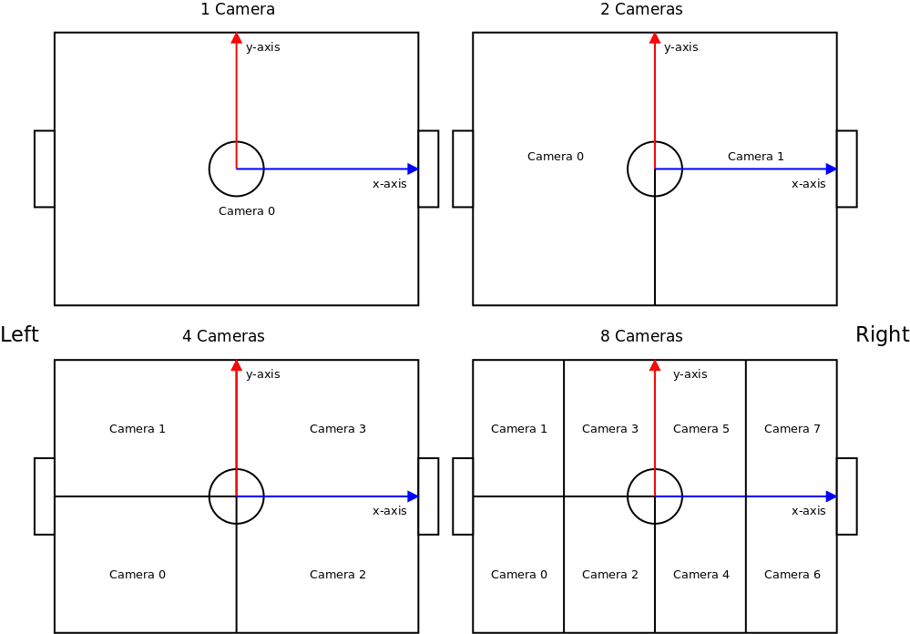
The cameras and the coordinate system in ssl-vision are set up as shown in the following figure. One instance of ssl-vision supports up to four cameras. Cameras are numbered from negative to positive coordinates.

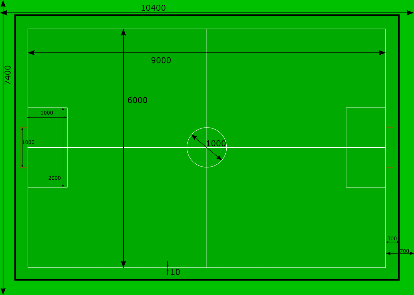
The field markings are specified as two lists, one of named line segments, and one of named circular arcs. To add / remove markings, change the number under the "Number of Line Segments" or "Number of Arcs" text entry. To reset the field markings to their defaults, click on the "Reset" button.

The default field markings are as prescribed in the rules book of RoboCup SSL

First, click on "Reset SSL 20XX" to reset the field markings.
The initial calibration of the cameras is performed by specifying control points in the image and their corresponding coordinates in the world. The default control points in the 4cam_experimental branch are the corners of each quadrant of the field, but the locations of the control point j for camera i may be changed to any other location from the setting "Camera i / Camera Calibrator / Calibration Parameters / Control point j", as shown in the screenshot below. To move the control points around in the image, make sure that the "Calibration" option under visualizations is checked, and that the camera calibration tab on the right is active.

- Enable the camera visualization and check the "camera calibration" and "calibration result" options.
- Select the camera calibration tab on the right, and click on "Reset".

- Drag the control points to the locations in the image that correspond to the specified world locations. In the screenshot below, the control points include the center of the field and the intersection of the defense arc and the goal line.
- Click on "Do Initial Calibration".

- Drag the camera height and camera distortion markers till the calibration result roughly approximates the actual field lines. Click on "Do Initial Calibration" again to update the initial calibration guess. Repeat to refine if required.

- Under the visualizations, turn on "Detected edges" and drag the "Line Search Corridor Width" slider on the calibration tab to increase the search corridors till they include the field markings. Click on "Detect additional points".

- The detected edges will be displayed. Now click on "Do full calibration" to calibrate using all detected points.
- If necessary, repeat the last 2 steps with a smaller corridor width to refine the calibration result. The final result should match will with the image, as shown below.
