Standalone receiver. To be used for manual flights. Number of Servo, PWM and discrete outputs can be configured.
See "ESP8266 plane" video: https://www.youtube.com/watch?v=c9dDOX0IzME
"Servo outputs" output 50Hz 1-2ms pulses.
"PWM outputs" output 8192Hz PWM signal, duty ratio 0...100. Usually used to connect brushed motors with simple ESCs which require PWM signal.
"Discrete outputs" output 1 (3.3V) or 0 (0V).
Transmits telementry: RSSI, battery voltage as A1.
Power supply voltage range is 3.1...6V. Receiver can be powered from 5V BEC, or directly from 1S battery: (4.2V-3.1V).
Peak power consumption is ~170mA.
No pulses on Failsafe (Servo, PWM). Discrete outputs keep last values.
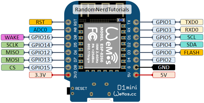
Onboard LED (D4 pin) is blinking if connection is estabilished. LED is disabled in failsafe mode.
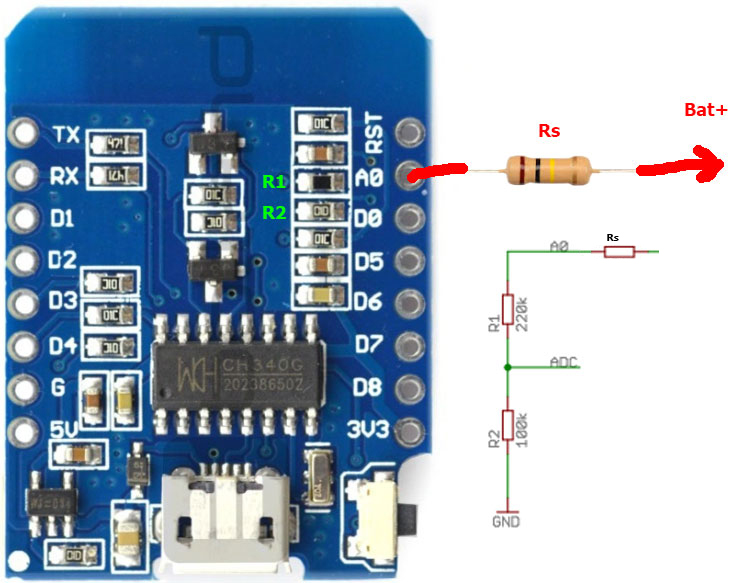
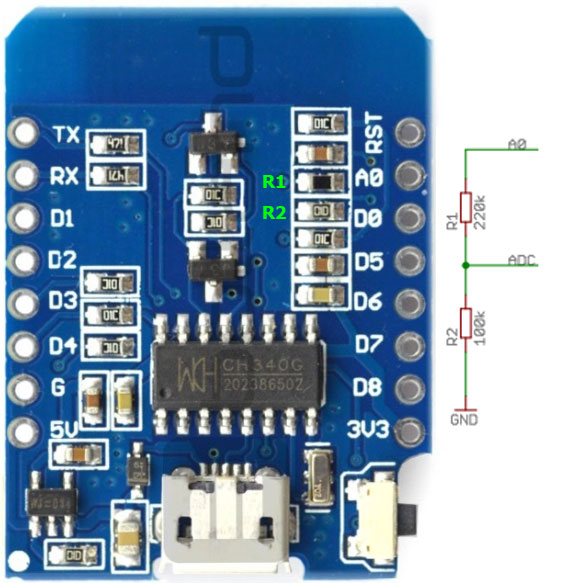
ESP8266 ADC voltage range is 0...1.0V. D1 Mini board contains voltage divider with 220k and 100k resistors to create voltage range 0...3.2V. In order to sense 1S or higher battery, additional series resistor is required.
Recommended resistor values (Rs):
1S - 220K (0-5.4V) 5V range have to be covered, since board can be connected to USB
2S - 680k (0-9V)
3S - 1.1M (0-13.2V)
4S - 1.5M (0-17.2V)
Another option is to replace one of the resistors of voltage divider on board.
Replacing 100k(R2) Resistor:
1S - 47k (0 - 5.6V)
2S - 20K (0 - 12V)
3S - 10K (0 - 20V)
4S - 10K (0 - 20V)
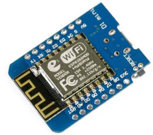
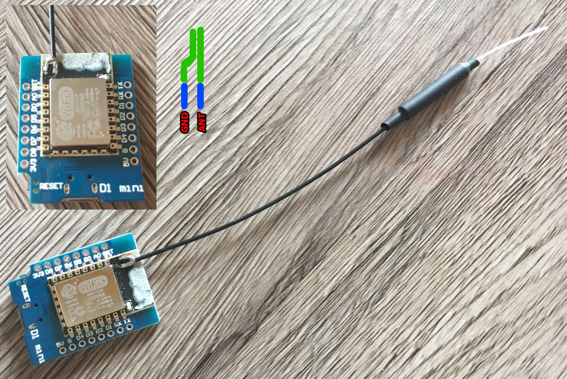
PCB antena provides range < 200m. It can be replaced with dipole or whip antenna for better range.
Remove PCB antena with dremel leaving only two solder pads for GND and signal. Solder Dipole antenna according to picture below.
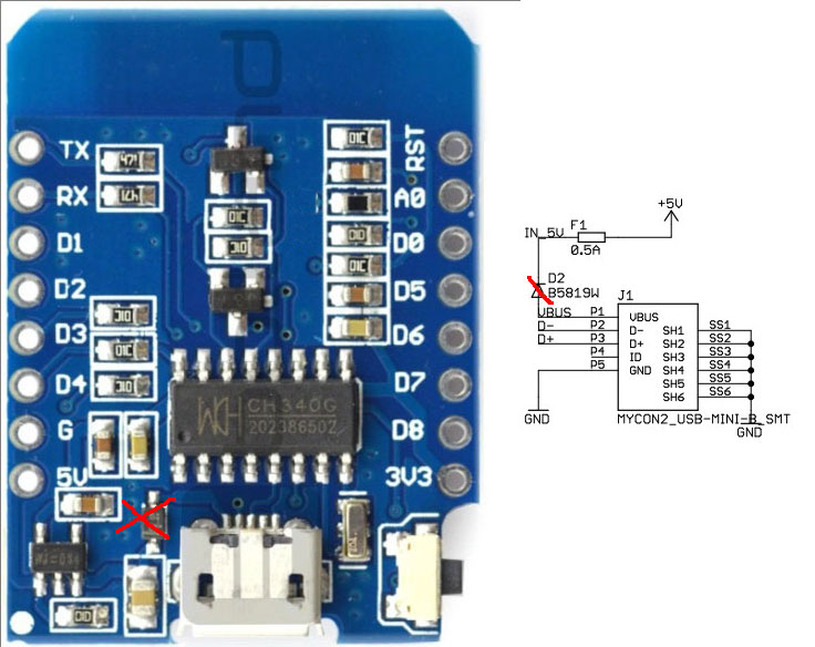
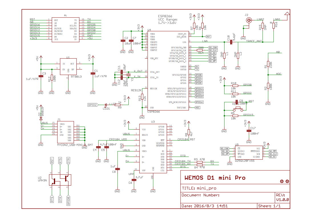
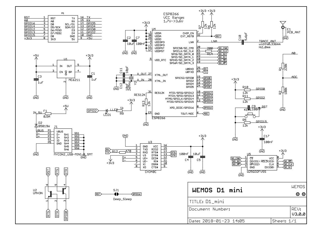
Diode D2 (see schematics below), from VBUS to +5V rail has to be removed.
This will convert D1 mini board from USB powered device to self-powered device.
Otherwise all devices connected to the same 5V BEC, or all devices in 1S configuration (servos, motors) will be powered from USB port. Diode will overheat and burn.
Note that 1S battery voltage is lower then 5V USB, so even with battery conected, all motors will be powered from USB.
With diode removed, it is safe to connect board installed on the plane to USB port. To flash, you have to connect battery to provide power to board.
Some D1 Mini board clones have too small capacitors on 3.3V rail.
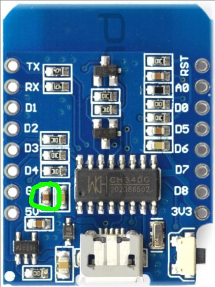
Motors generate a lot of noise. If board reboots or terminal looses connection, add additional 20uF capacitor between 3.3V and GND rails.
Anternatively, repace 1uF capacitor on board with 20uF capacitor:
Receiver supports beeping using brushed motors. Obviously, beeping is possible when motor throttle is down only. Receiver will enable beep beacon:
- after FILSAFE_BEEP_DELAY_MS delay in failsafe mode.
- after IDLE_BEEP_DELAY_MS delay with throttle down.
- if MOTOR_BEEPER_CH(zero-based channel number) has value>1750. In this mode motors beeps with high volume, and can turn a little.
Beeping with brushless motors is not supported. Use BLHeli feature for idle beep beacon.
- edit receiver configuration: examples/rx_d1_mini_pwm/include/rx_config.h:
- configure key and wifi channel (USE_KEY, USE_WIFI_CHANNEL)
- configure output pins (SERVO_PINS, PWM_PINS, DISCRETE_PINS)
- flash examples/rx_d1_mini_pwm/ to D1 Mini board
- replace voltage sensing resistor
- remove diode
- repace capacitor or add additional capacitor to 3.3V rail for stability
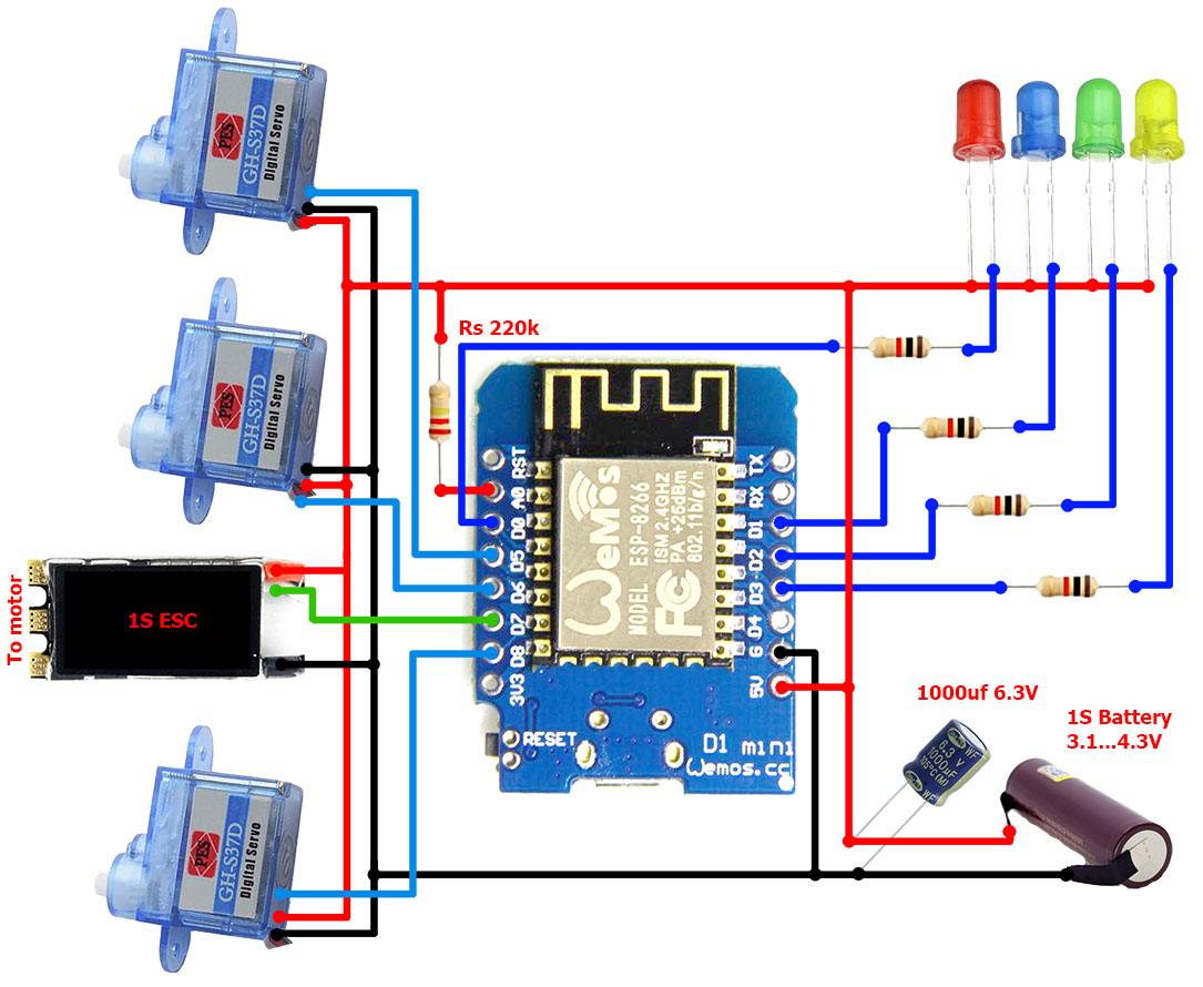
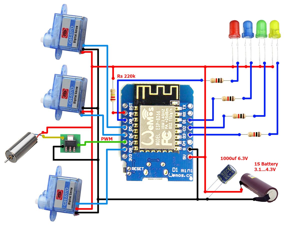
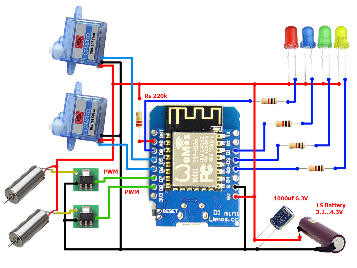
Three example configurations are provided below.
4 Servo outputs: AETR. ESC calibration is enabled on Channel 4.
4 Discrete outputs.
*for 2S and higher battery, 5V Beck is required to power servos and receiver.
3 Servo outputs: AETR.
Channel 4 outputs PWM for simple brushed ESC.
4 Discrete outputs.
2 Servo outputs: AETT.
Channels 3 and 4 output PWM for simple brushed ESCs.
4 Discrete outputs.
https://randomnerdtutorials.com/esp8266-pinout-reference-gpios/
ESP8266 operating voltage range is 3.0v - 3.3V. Maximum power consumption is ~300mA. Board contains LDO regulator ( 250mV on 500mA ). This allows to run board directly from 1S battery. In practice, it runs fine down to 3.1V.
Module based on cp2104:
Module based on CH340C:
There are also modules based on CH340G.
