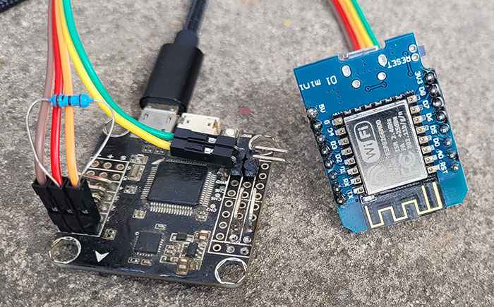
Receiver to be used with flight controller. Receives 15 channels and outputs SBUS signal. Transmits bidirectional transparent telemetry stream (can be used for Mavlink, LTM, MCP etc.).
RSSI is injected into channel 16.
Can be powered from 5V BEC.
Peak power consumption is ~170mA.
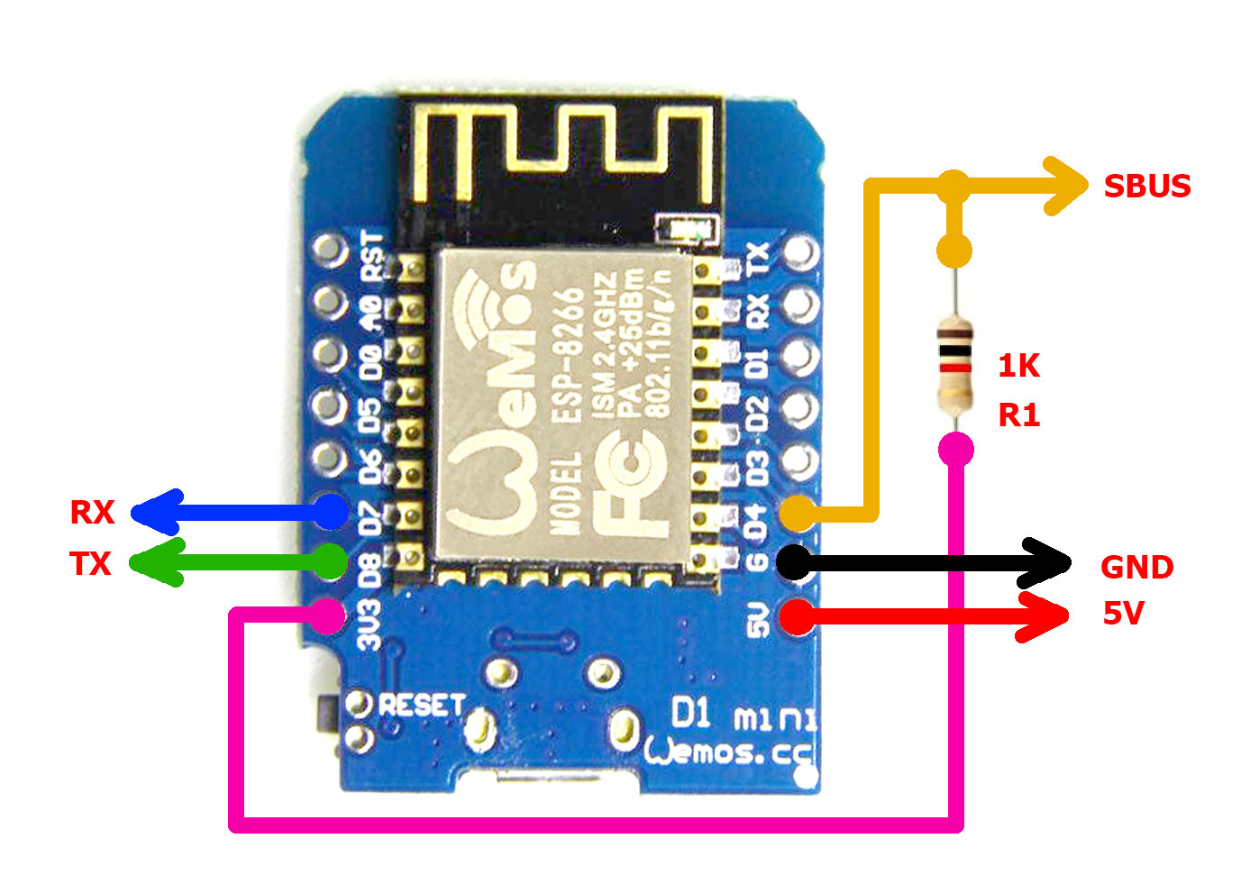
Receiver is similar to rx_esp01_sbus. The only difference is that Serial1 pins are swapped to pins D7/D8, because Serial1 is connected to USB serial.
See testing ESP01 receiver with INAV 1.7.3 flying wing: https://www.youtube.com/watch?v=UptvxsFHDFA
Failsafe flag is passed in SBUS packets. Channels retain last good values.
- Wemos D1 Mini board
- 1k 1/8W resistor
- dipole or whip antenna (optional)
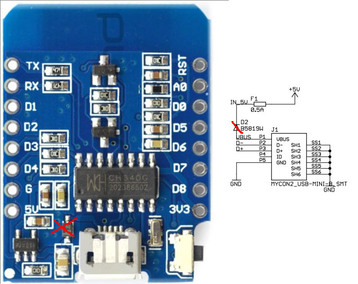
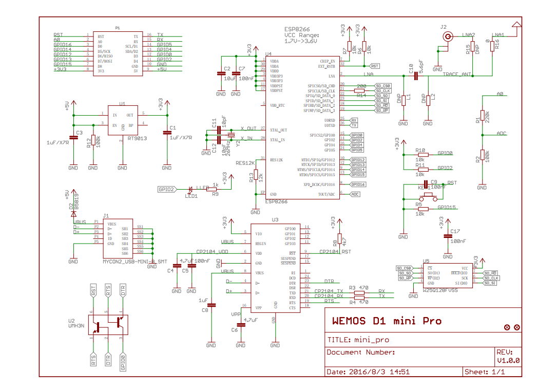
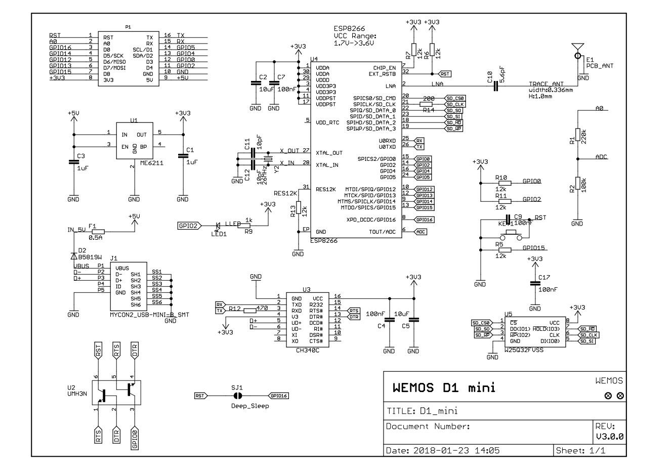
Diode D2 (see schematics below), from VBUS to +5V rail has to be removed.
This will convert D1 mini board from USB powered device to self-powered device.
Otherwise all devices connected to the same 5V BEC will be powered from USB port.
With diode removed, it is safe to connect board installed on the plane to USB port. To flash, you have to connect battery to provide power to board.
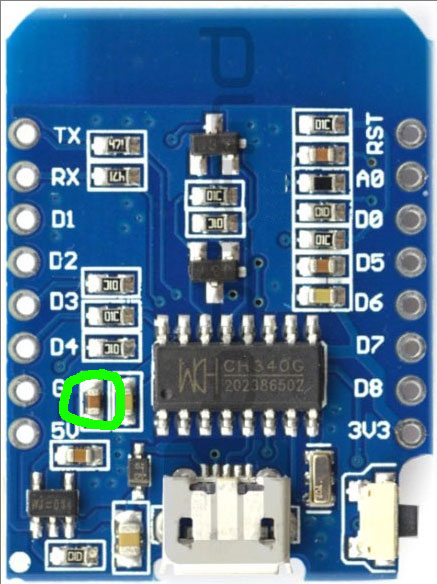
Some D1 Mini board clones have too small capacitors on 3.3V rail.
Motors generate a lot of noise. If board reboots or terminal looses connection, add additional 20uF capacitor between 3.3V and GND rails.
Anternatively, repace 1uF capacitor on board with 20uF capacitor:
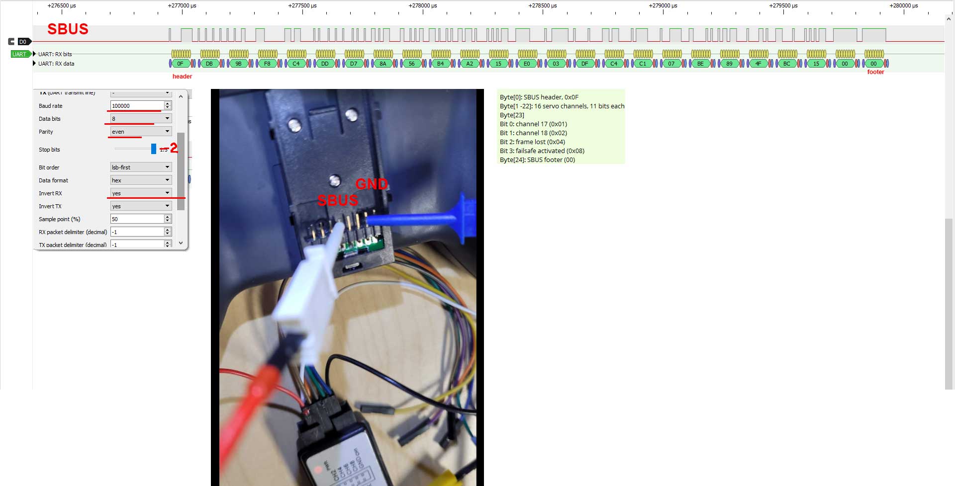
SBUS output is GPIO2. If GPIO2 is pulled down, ESP8266 boot fails. Typical SBUS invertor schematix on flight controller includes 1k resistor to the base/gate of transistor and 10k pulldown resistor from base/gate to GND. Effectively, GPIO2 is grounded. The easiest way to solve this is to add 1k pullup resistor.
If ESP is still not able to boot, and boots with GPIO2 disconnected from FC, then R1 value should be decreased, down to 470 Ohm. Alternativelly, connect GPIO2 to FC through diode (cathode to ESP8266).
-
Solder R1
-
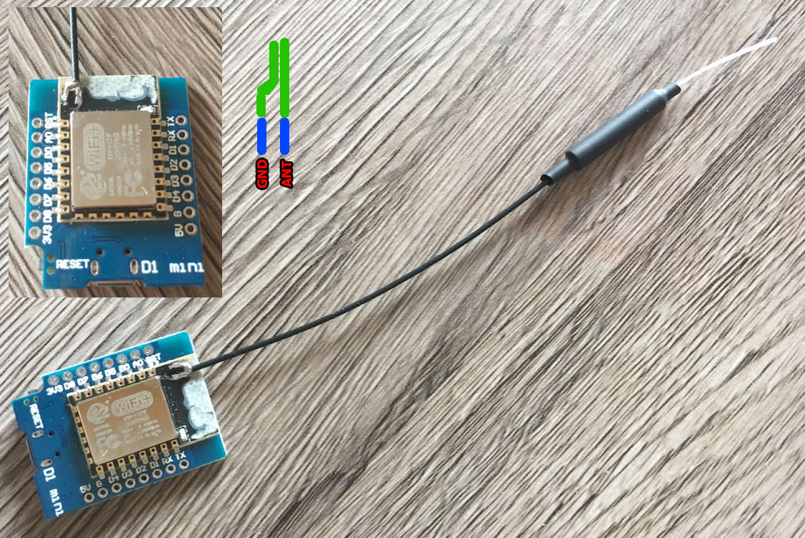
Remove PCB antenna using dremel, leaving two small pins only (optional) and solder dipole or whip antenna (optional).
- Flash firmware
- Edit receiver configuration:
examples/rx_d1_mini_sbus/include/rx_config.h
- configure key and wifi channel:
USE_KEYandUSE_WIFI_CHANNEL - configure telemetry baudrate
- Upload
examples/rx_d1_mini_sbus/project using PlatformIO.
After initial flashing, firmware can be updated wirelessly (OTA).
When transmitter is not working, it is possible to update receiver.
- Connect to access point "hxrcrsbus" without password.
- Uncomment:
upload_protocol = espota

upload_port = 192.168.4.1
lines in platformio.ini.
- Build and upload using PlatformIO IDE as usual.
ESP8266 operating voltage range is 3.0v - 3.3V. Maximum power consumption is ~300mA. Board contains LDO regulator ( 250mV on 500mA ). This allows to run board directly from 1S battery. In practice, it runs fine down to 3.1V.
Module based on cp2104:
Module based on CH340C:
There are also modules based on CH340G.
