A network tester for LoRaWAN networks.
This is designed to work with the following hardware:
- Adafruit Feather M0 (ATSAMD21)
- Microchip RN2483
- GPS (nema encoding e.g. Ubox or Quectel L80)
- Analog joystick.
- 1.8TFT ST7735 Display
- NeoGPS
- RN2483 (Forked from arduino-device-lib by TTN)
- FlashStorage
- Arduino Serial Command (Already included as we overwritten bits)
- Adafruit GFX
- Adafruit ST7735
- Axis Joystick
Hardware specific changes can be made to the "hardware.h" file. Upload this sketch to your Feather M0 using the Arduino IDE. Your IDE must have the Adafruit SAMD boards support added for this to work.
On boot you will be presented with the "Menu" screen containing the following functions:
You can move between menu items by pushing up/down on the joystick. Click the joystick to activate the currently selected item. "Survey" and "Sweep" will not be available (marked with an 'X', rather than '>') if the required LoRaWAN network keys for the currently selected join mode are not present; see USB and Settings - join
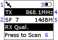
"Survey" is a mode that utlises the current device settings to perform periodic or manual transmissions. If the device has been configured to join using "Over The Air Activation", and is currently not connected to a network, entering this mode the device will first attempt to join a network using the internal device keys. "Survey" mode is great for performing "war driving" tests.
- GPS Status (Disconnected)
- Spread factor of current transmission
- Battery Status (Half-full)
- The current operation frequency of the device
- The current transmission power of the device
- "Press to Scan" when in manual mode / RX Qual results when TX successful and acknowledged (Sweep, See 3 and 8)
Pushing the joystick to the left when in survey mode will return the device to the menu
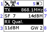
"Sweep" is a mode that causes the device to send a transmission at each spreadfactor (SF7 - SF12, i.e. DR5 - D0); this collection of transmissions is referred to as a 'test'. This mode is useful for testing connectivity at a specific location (e.g. before deploying a sensor). If the device has been configured to join using "Over The Air Activation", and is currently not connected to a network, entering this mode the device will first attempt to join a network using the internal device keys. Because of duty cycle limitations, the device may have to wait for a free-channel before it can attempt a transmission at a specific spreadfactor. During this time the device will state "No Free Chan. Cancel Test?", clicking the joystick will cancel the current and subsequent transmissions left in the test.
- GPS Status (Connected)
- Spread factor of current transmission
- The current link margin, calculated from the signal recieve strength
- The device is actively transmitting
- Battery Status (Half-full)
- The current operation frequency of the device
- The current transmission power of the device
- The number of gateways that sucessfully recieved the message
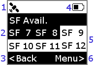
At the end of the test the results will be displayed on the screen. Transmissions that were successful and therefore recieved an acknowledgement from a network server will be presented as black text on a white background. Transmissions that were not successful, because they did not recieve an acknowledgement, will be presented as white text on a black background.
From this menu you can either push left on the joystick to intiate a new test or push right to return to the main menu.
- GPS Status (Connected)
- Spread factors that were not acknowledged
- Start a new test
- Battery Status (Half-full)
- Spread factors that were acknowledged
- Return to menu
"Settings" lets you configure the runtime settings of the device. Upon entering this menu option you will be presented with the following configurable settings:
Pushing right or left on the joystick of a currently selected setting will alter that setting. Pushing up or down on the joystick allows you to move between different settings.
This allows you to change the current join mode of the device. This can either be OTAA (Over the Air Activation) or ABP (Activation by Personalisation). OTAA means that the device will perform a join-procedure with the network during which security keys and a dynamic DevAddr is assigned. Because of this, OTAA requires the presence of a network. ABP hardcodes the DevAddr and security keys in the device. This allows the device to "skip" the join procedure.
Choosing between OTAA is your choice and if you have provisioned your device with both sets of keys then you can move between them at will. If you are starting in a place with known network connectivity, OTAA may be an easier, preferred option. If you are starting from a place without network connectivity, but may move into range during a survey or sweep, then you may prefer to use ABP. If you do use ABP, you will likely need to inform your network server to have "relaxed frame counts", as power cycles will likely loose this information and therefore prevent further sucessful transmissions.
The "join-procedure" is only initiated when you enter "Survey" or "Sweep", so you can configure this setting at anytime.
"SF" (Spread Factor) allows you to adjust the spread factor used for joins and survey transmissions. Selectable spreadfactors range from 7 to 12 (data rates 5 to 0). This spreadfactor video explains spreadfactor and its influence.
"TX IVL" (TX Interval) allows you to adjust the frequency of periodic transmissions whilst in "Survey" mode. The available options are: Man, 1 second, 2 seconds, 5 seconds, 10 seconds, 30 seconds, 1 minute, 2 minutes, 5 minutes, 10 minutes. When set to "Man" (Manual), the device will not perform periodic transmission; instead, it will require manual activation by clicking the joystick.
Exits the "Settings" menu if the joystick is clicked when this option is currently selected. Upon leaving the "Settings" menu you will be asked if you wish to "Save as Default?" the current settings. Selecting "Yes" will store the settings on the internal flash, allowing them to persist between device restarts. The flash is limited to around 10K writes. Selecting "No" means the current settings will only persist until the device restarts (at which point the default settings will be restored).
"USB" mode allows you to configure the device using the serial interface (e.g. the one provided by the Arduino IDE, CoolTERM, etc.). Upon entering this mode, you will be able to send a commands to the device. This is how you provision the device with the required network keys.
The commands available in this mode are:
When a command expects one or more parameters, the start of each parameter is delimited with a space. A new line and carriage return is required to send the command to the device.
Configures the keys required for OTAA (Over the Air Activation). This command expects 16 characters for the appEui and 32 characters for the appKey. These should be available from your network server. In some cases appEui is not provided, in these cases try using "0000000000000000". Spaces are used to mark the start of each key, you do not need the quotes or brackets!
This command should return "OK" if the device accepted and saved the keys to the RN2483 (this will persist between restarts). It will return invalid if there is a problem with your keys (e.g. you didn't specify one / wrong length) or the RN2483 rejected them.
Configures the keys required for ABP (Activation by Personalisation). This command expects 8 characters for the devAddr, 32 characters for the NwksKey and 32 characters for the AppsKey. These should be available from your network server. Spaces are used to mark the start of each key, you do not need the quotes or brackets!
This command should return "OK" if the device accepted and saved the keys to the RN2483 (this will persist between restarts). It will return invalid if there is a problem with your keys (e.g. you didn't specify one / wrong length) or the RN2483 rejected them.
This commands returns the hardware EUI of the RN2483. This is required when registering a device with a network server. We use the HWEUI and this is unique to the RN2483, rather than depending on the user to try and come up with their own.
This commands exits "USB" mode and returns you to the main menu.
GNU Ver 3.
- Icons used:
- USB - Icon made by Smashicons from www.flaticon.com
- Battery - Icon made by Smashicons from www.flaticon.com
- Satellite - Icon made by FreePic from www.flaticon.com
- Transmitting - Icon made by photo3idea_studio from www.flaticon.com


