Download "RASPBIAN JESSIE LITE" https://www.raspberrypi.org/downloads/raspbian/
Create your new hard disk for DashboardPI
Insert the microSD to your computer via USB adapter and create the disk image using the
ddcommandLocate your inserted microSD card via the
df -hcommand, unmount it and create the disk image with the disk copyddcommand$
df -h/dev/sdb1 7.4G 32K 7.4G 1% /media/XXX/1234-5678$
umount /dev/sdb1Caution: be sure the command is completely accurate, you can damage other disks with this command
if=location of RASPBIAN JESSIE LITE image file of=location of your microSD card
$
sudo dd bs=4M if=/path/to/raspbian-jessie-lite.img of=/dev/sdb(note: in this case, it's /dev/sdb, /dev/sdb1 was an existing factory partition on the microSD)
Setting up your RaspberriPi
Insert your new microSD card to the raspberrypi and power it on with a monitor connected to the HDMI port
Login
user: pi pass: raspberry
Change your account password for security
sudo passwd pi
Enable RaspberriPi Advanced Options
sudo raspi-config
Choose:
1 Expand File System
6 Enable Camera
9 Advanced Options
A2 Hostnamechange it to "SunRise"
A4 SSHEnable SSH Server
A7 I2CEnable i2c interface
Enable the English/US Keyboard
sudo nano /etc/default/keyboard
Change the following line:
XKBLAYOUT="us"
Reboot PI for Keyboard layout changes / file system resizing to take effect
$
sudo shutdown -r now
Auto-Connect to your WiFi
sudo nano /etc/wpa_supplicant/wpa_supplicant.conf
Add the following lines to have your raspberrypi automatically connect to your home WiFi (if your wireless network is named "linksys" for example, in the following example)
network={
   ssid="linksys"
   psk="WIRELESS PASSWORD HERE"
}
Reboot PI to connect to WiFi network
$
sudo shutdown -r nowNow that your PI is finally on the local network, you can login remotely to it via SSH. But first you need to get the IP address it currently has.
$
ifconfigLook for "inet addr: 192.168.XXX.XXX" in the following command's output for your PI's IP Address
Go to another machine and login to your raspberrypi via ssh
$
ssh pi@192.168.XXX.XXX
Start Installing required packages
$
sudo apt-get update$
sudo apt-get upgrade$
sudo apt-get install vim git python-smbus i2c-tools python-imaging python-smbus build-essential python-dev rpi.gpio python3 python3-pip libi2c-dev python-picamera python-opencv
Update local timezone settings
$
sudo dpkg-reconfigure tzdata
select your timezone using the interface
Setup the simple directory l command [optional]
$
vi ~/.bashrcadd the following line:
$
alias l='ls -lh'$
source ~/.bashrc
Fix VIM default syntax highlighting [optional]
$
sudo vi /etc/vim/vimrcuncomment the following line:
syntax on
Clone SunRise repository
$ cd ~
$ https://github.com/khinds10/SunRiseCatcher.git
Install the SSMTP mail program to gmail your sunrise pictures
$
sudo apt-get update && apt-get install ssmtp
$
sudo apt-get install sharutils
Edit the SSMTP config
$
sudo vi /etc/ssmtp/ssmtp.conf
comment out:
mailhub=mailcomment out:FromLineOverride=YES
Add the following lines to the end of the file
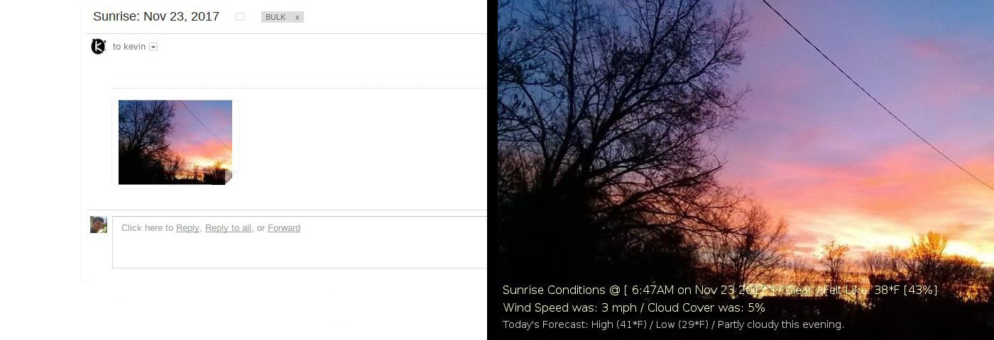
AuthUser=your-gmail-address@gmail.comAuthPass=YOUR GMAIL PASSWORDFromLineOverride=YESmailhub=smtp.gmail.com:587UseSTARTTLS=YES
Test emailing to yourself using the installed command
$
echo "This is a test" | mail -s "Test" your-gmail-address@gmail.com
Digole 1.8" Serial:UART/I2C/SPI True Color TFT LCD 160x128 Display Module for Arduino/PIC/AVR/PI

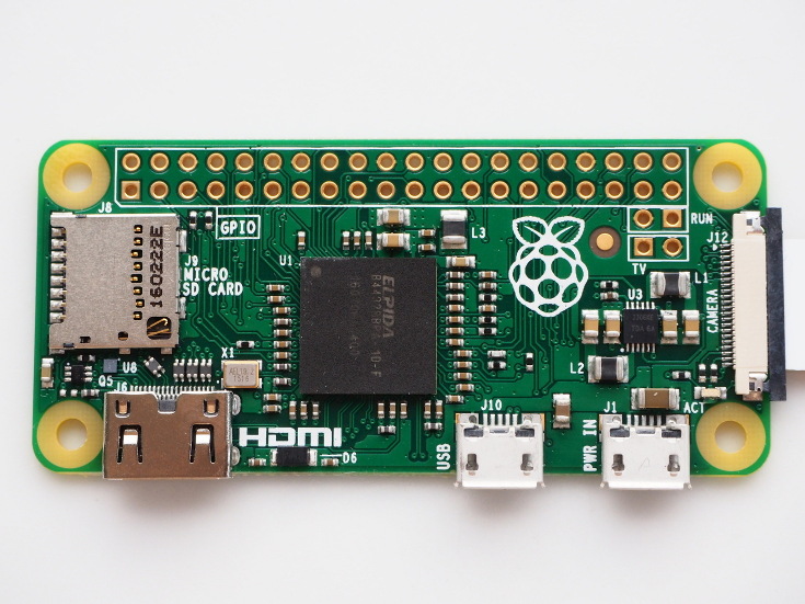
RaspberriPi Zero (W Model w/ built in wireless)
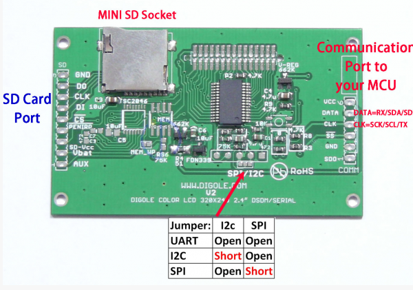
Prepare the Digole Display for i2C
On the back of the Digole Display, solder the jumper to assign the display to use the i2c protocol
Digole Display
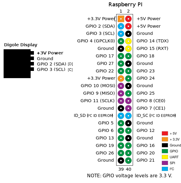
Connect the display to the RPi as follows using the below diagram
GND -> GND
DATA -> SDA
CLK -> SCL
VCC -> 3V
Using a 3D printer print the enclosure files included in the 'enclosure/' folder. .x3g files are MakerBot compatible. You can also use the .stl and .blend (Blender Program) files to edit and create your own improvements to the design.
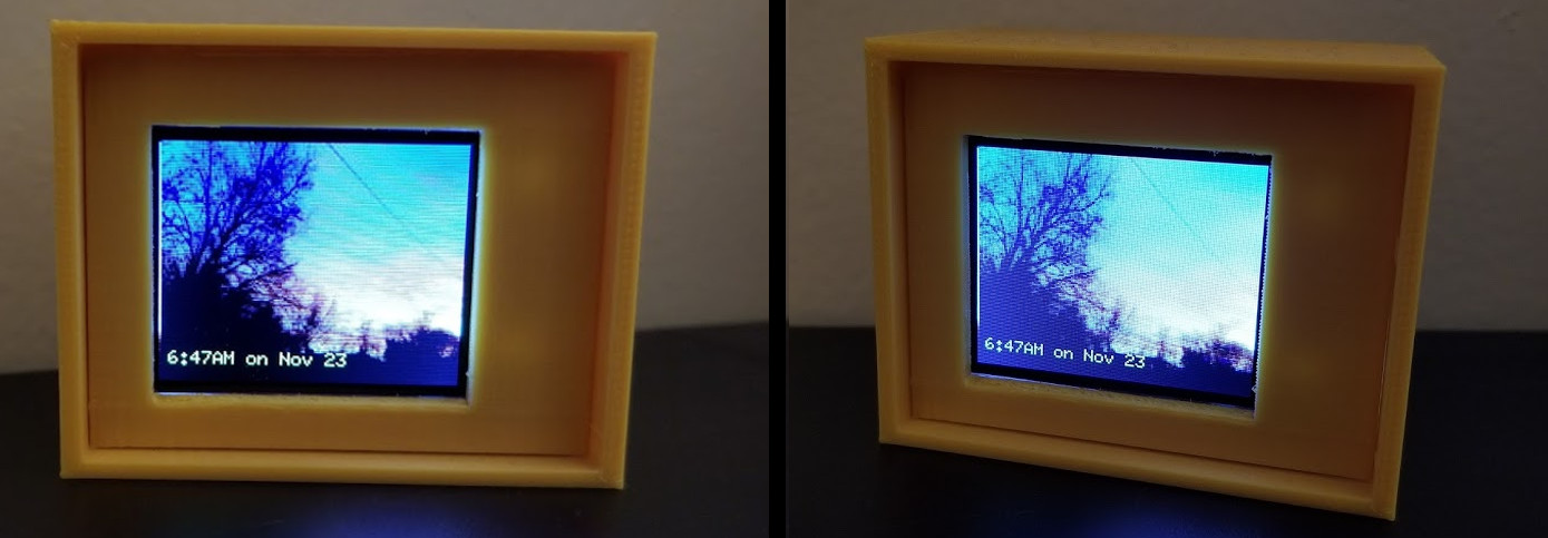
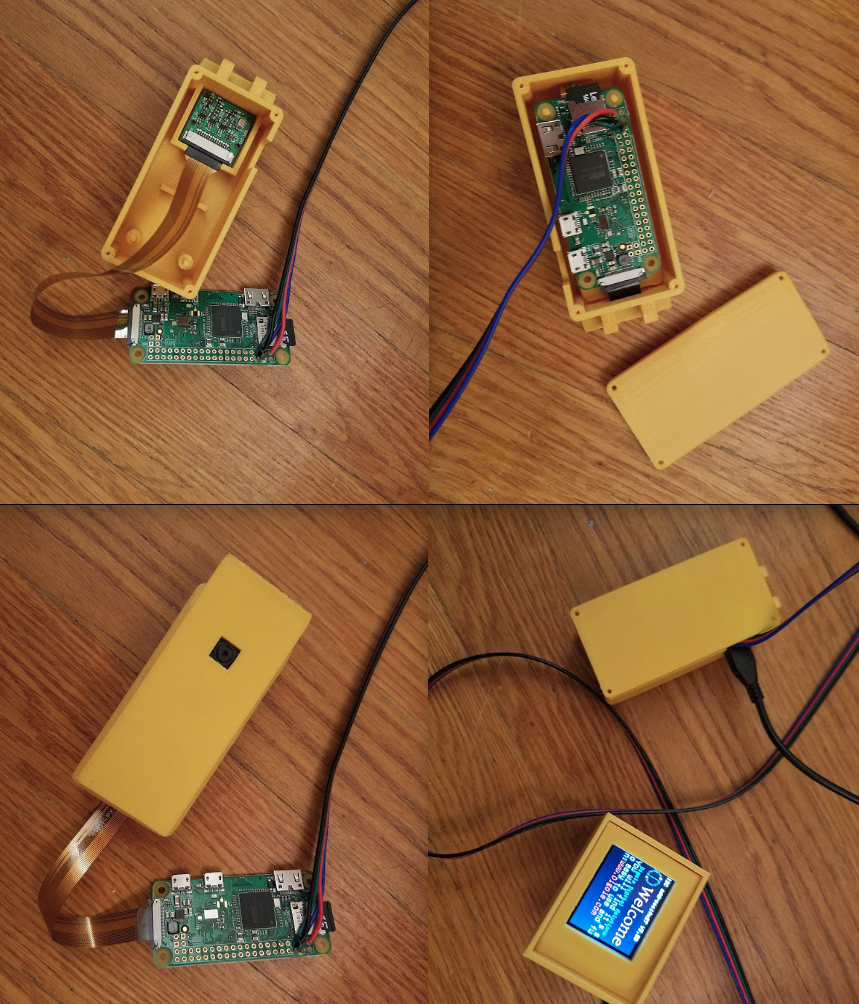
Put the camera and the pizero in the case, attach the front panel to cover any marks from the printing process
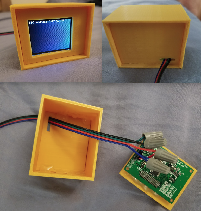
Glue the display to the front panel of the display box and put the wiring through the back hole
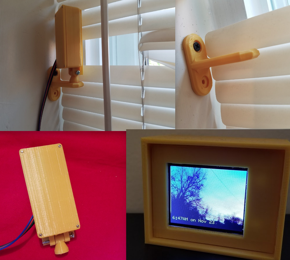
Mount the display in an eastern facing window
Change your settings.py to match your personal preferences
settings.py
emailAddress = 'your-email@gmail.com'
weatherAPIURL = 'https://api.forecast.io/forecast/' weatherAPIKey = 'YOUR FORECAST.IO KEY HERE'
numberOfSunriseCaptures = 15 timeToCaptureMinutes = 30
latitude = 42.4152778 longitude = -71.1569444
Run Daily at 4am (via crontab)
Add the following line to your PI crontab to run the capture program starting at 4am
$
crontab -e0 4 * * * python /home/pi/SunRiseCatcher/capture.py > /home/pi/SunRiseCatcher/capture.out
