The project centers on crafting a safety headgear tailored for underground tunnel workers. Key features include real-time location tracking and monitoring of temperature, pressure, and air quality. The primary goal is to enhance worker safety in the face of potential hazards like temperature fluctuations, pressure changes, or exposure to gases during tunneling incidents. Wireless communication facilitates connectivity between tunnel workers and the external world, with GPS technology ensuring precise location tracking for emergency response. The design prioritizes portability, cost-effectiveness, and durability to meet the specific needs of underground tunnel workers.
Overview
This project comprises two primary components: the Helmet Unit and the Control Unit. Arduino is the cornerstone for developing our mining tracking and safety helmet system. The key objectives involve acquiring real-time data such as location, temperature, air quality, and pressure. A robust communication system has been established between the underground miners' safety helmets and the main control unit situated on the ground surface. The programming for the entire system is done using the C programming language.
The Control Unit predominantly functions as a receiver, while the Helmet Units primarily act as transmitters, relaying location data and other pertinent information. Notably, all three units in the system can operate interchangeably as both transmitters and receivers, showcasing a versatile communication network. This GitHub repository provides the codebase and documentation for seamless understanding and utilization of the project.
Technologies, Software, and Main Hardware Components Used
RF Wireless Technology
Utilized for wireless communication, RF technology operates in the electromagnetic spectrum's radio wave frequencies, providing communication channels without the need for an air-based medium.
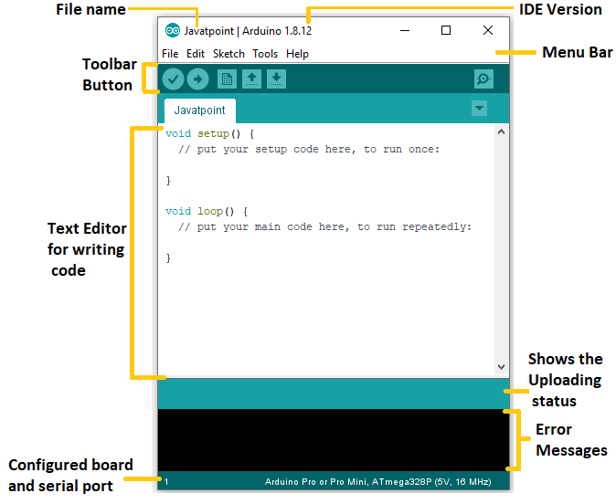
Arduino IDE
The Arduino Integrated Development Environment (IDE) is the software platform for programming and uploading code to the Arduino hardware. It facilitates communication and programming of the Arduino UNO microcontroller.
NRF24L01+PA+LNA 2.4G Wireless Transceiver Module with SMA Antenna
The NRF24L01 module facilitates wireless communication between the reporting and helmet sections, operating at 2.4 GHz ISM Band with a baud rate of 250 kbps - 2 Mbps. It allows for easy data transmission and reception.
Arduino UNO Microcontroller
The Arduino UNO R3 microcontroller, equipped with 14 digital pins, PWM outputs, and six analog inputs, serves as the project's control unit. It features a 16 MHz crystal oscillator, USB port, power jack, ICSP header, and a reset button.

MQ135 Air Quality Gas Sensor Module
The project incorporates the MQ-135 digital sensor to measure air quality in parts per million (PPM). This sensor detects various gases in the atmosphere, signaling when gas levels exceed predefined thresholds.

MPU-6050 Triple Axis Analog Accelerometer Gyroscope Module
The MPU6050 sensor module, a 6-axis motion tracking system, includes a 3-axis gyroscope, a 3-axis accelerometer, and a temperature sensor. It communicates via an I2C bus interface and provides accurate temperature readings.

BMP180 Pressure Sensor
The BMP180 high-precision sensor measures barometric pressure digitally, accounting for temperature variations. It is utilized to monitor pressure in underground tunnels.

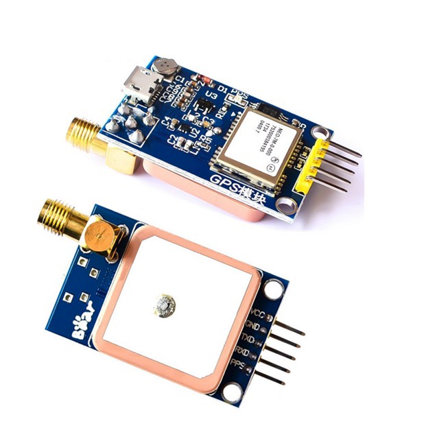
NEO-7M GPS Module with Antenna
The NEO-7M GPS module employs Ublox technology and a built-in active GPS antenna. It provides accurate positioning data, enhancing performance with multirotor control platforms.
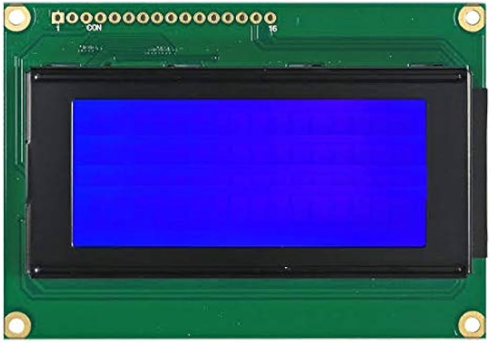
16x4 LCD Display
The 16x4 LCD display is employed to showcase outputs from oxygen, carbon dioxide, and temperature sensors. It is chosen for its programmability, ability to display custom characters, and cost-effectiveness.
I2C module
Leveraging the I2C module simplifies LCD display control, streamlining communication through a two-wire interface. This method enhances efficiency in managing and presenting information on the LCD screen with reduced wiring complexity.

Power Source
To ensure continuous operation underground, rechargeable batteries and power banks with a capacity of 10,000mAh and 5V are used. The system can run for approximately 27 hours, providing an alternative power source in case of a power failure.
Helmet Unit Component Connections to Arduino:
-
nRF24L01 Module:
- CE (Chip Enable): 9
- CSN (Chip Select Not): 10
- SCK (Serial Clock): 13
- MO (Master Out): 11
- MI (Master In): 12
-
MPU6050 Module:
- SCL (Serial Clock Line): A5
- SDA (Serial Data Line): A4
-
MQ135 Sensor:
- Analog Output (A0): A0
-
Neo-7M GPS Module:
- TXD (Transmit Data): 4
- RXD (Receive Data): 3
-
BMP180 Sensor:
- SDA (Serial Data Line): SDA
- SCL (Serial Clock Line): SCL
Control Unit Component Connections to Arduino:
-
nRF24L01 Module:
- CE (Chip Enable): 9
- CSN (Chip Select Not): 10
- SCK (Serial Clock): 13
- MO (Master Out): 11
- MI (Master In): 12
-
16x4 LCD Display:
- SDA (Serial Data Line): A4
- SCL (Serial Clock Line): A5
Insert gif or link to demo