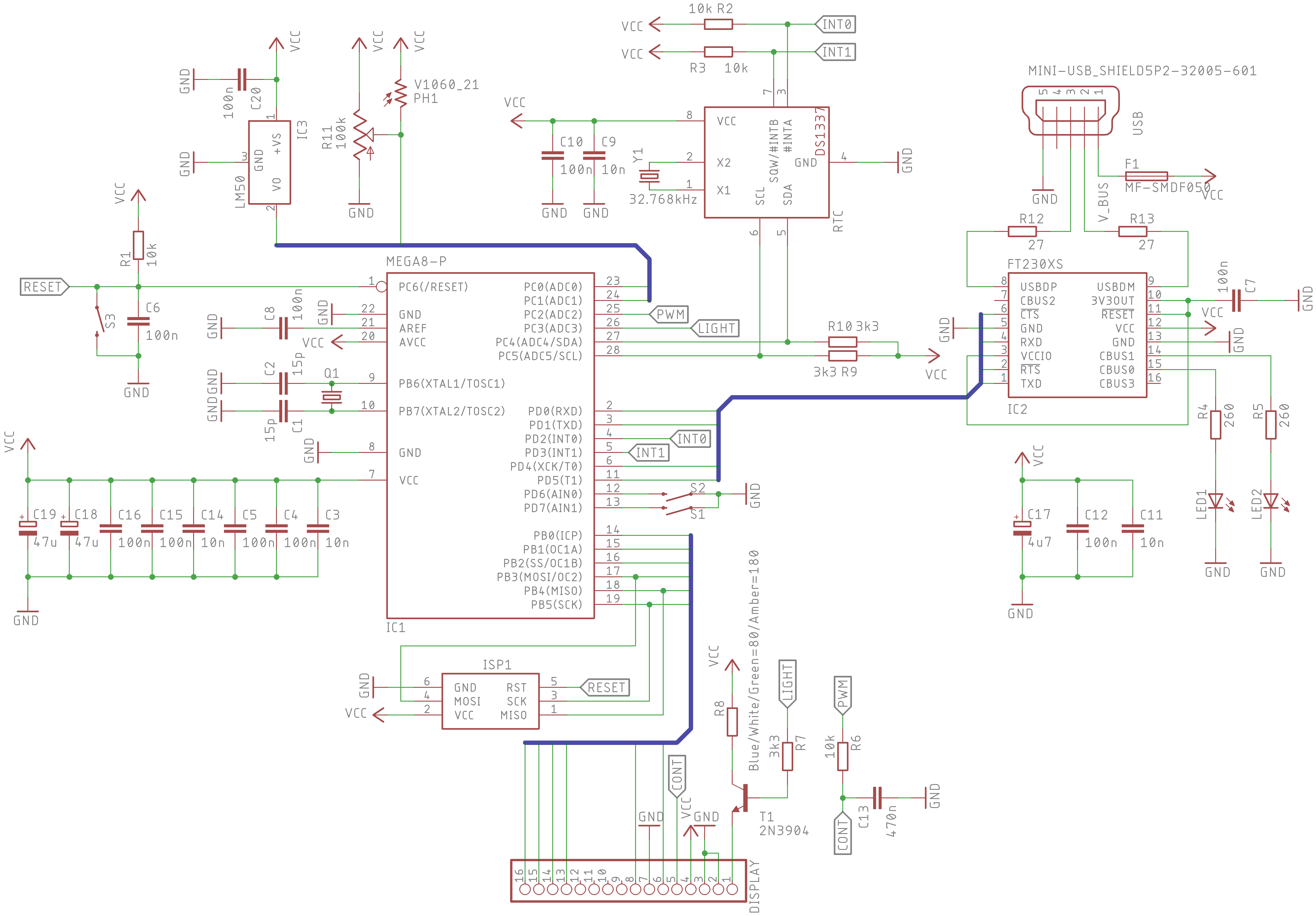
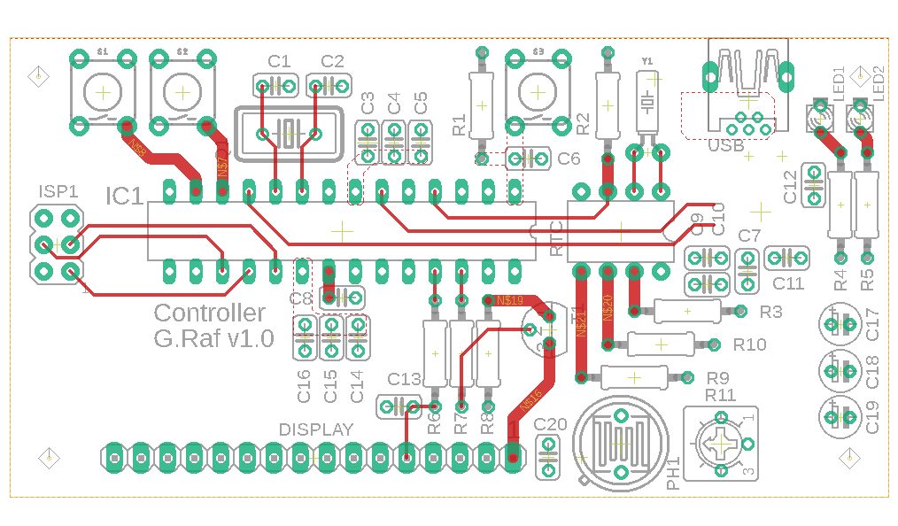
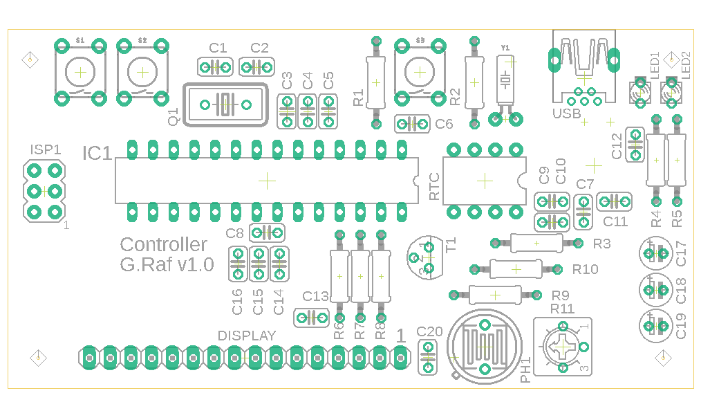
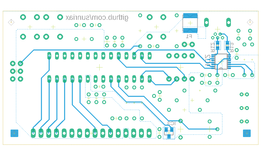
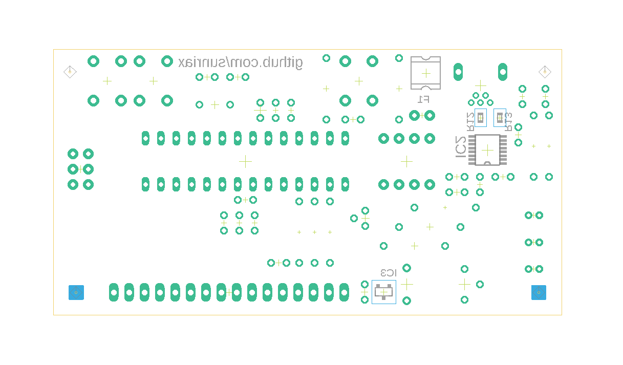
The controller layout is designed to adapt an LCD Display (e.g. Displaytech 162A/B) and control Text and other stuff through USB (UART). It can be powered through the mini USB jack. If the controller is used the first time, it it necessary to throw the Bootloader on the chip.
In Firmware repository the additional software to control the display is stored.
| PIN | Function | Description |
|---|---|---|
| 1 | A | Backlight anode |
| 2 | K | Backlight cathode |
| 3 | VSS | Ground (0V) |
| 4 | VDD | Supply voltage (5V) |
| 5 | VO | Contrast Voltage |
| 6 | RS | HIGH=Data Signal/LOW=Instruction Signal |
| 7 | R/W | Connected to ground (0V) |
| 8 | E | Chip enable signal |
| 9 | DB0 | Data bit 0 (not connected) |
| 10 | DB1 | Data bit 1 (not connected) |
| 11 | DB2 | Data bit 2 (not connected) |
| 12 | DB3 | Data bit 3 (not connected) |
| 13 | DB4 | Data bit 4 |
| 14 | DB5 | Data bit 5 |
| 15 | DB6 | Data bit 6 |
| 16 | DB7 | Data bit 7 |
| PIN | Function | Description |
|---|---|---|
| 1 | MISO | Master In/Slave Out |
| 2 | VCC | Power supply for ISP programming |
| 3 | SCK | Clock input |
| 4 | MOSI | Master Out/Slave In |
| 5 | RESET | System reset |
| 6 | GND | Ground connection |
Necessary parts to build the board are documented in the THT and SMD bill of material list. We recommend to buy the parts at RS-Components. The related numbers are deposited at the bill of material lists.
