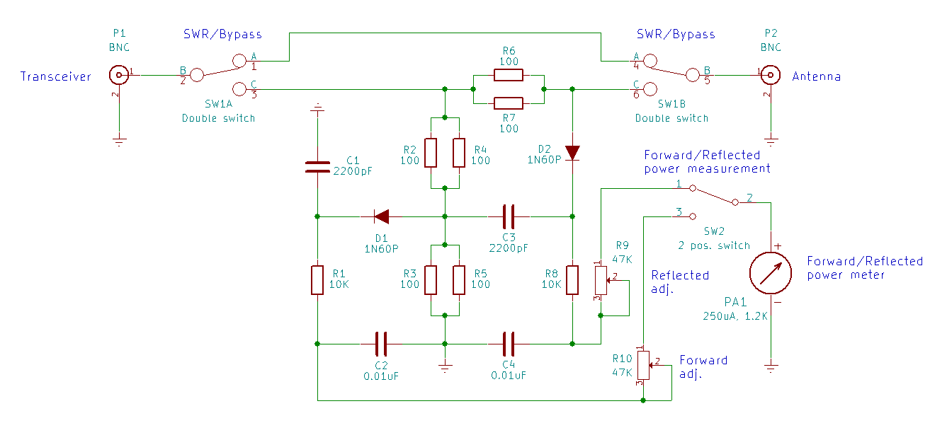
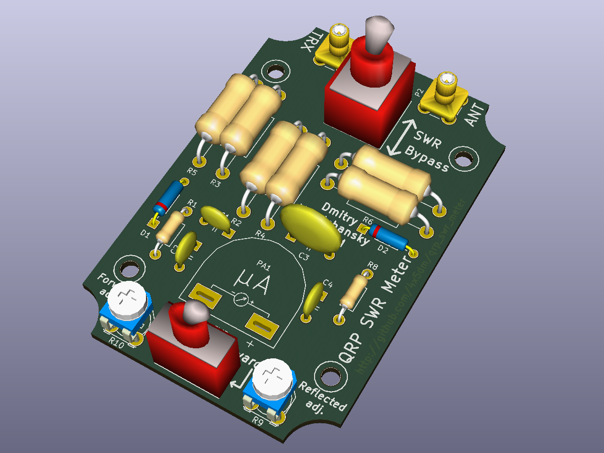
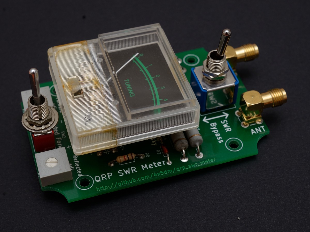
This QRP SWR meter was designed for using with my Yaesu FT-817ND transceiver. Actually, it is antenna impedance meter based on Wheatstone bridge where antenna represents the unknown resistance. The bridge is built with six 2W resistors thus it can handle up to 16W of transmitting power.
This SWR-meter design has one big disadvantage: each time when SWR measurement is required, the device has to be switched from bypass to measurement mode. After antenna tuner alignment it has to be switched to bypass mode again. Real-time SWR monitoring is impossible with this type of SWR-meters. However, the Wheatstone bridge uses widely available resistors and does not require winding any coils. It makes such devices easy to build and can be considered an advantage.
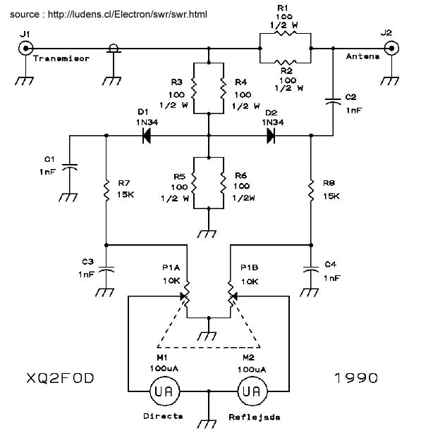
This project is not the first of this kind. My main source of inspiration was Wideband SWR meter by Manfred Mornhinweg XQ6FOD.
Other similar circuits can be found in links section of this document and on the internet.
In general, this circuit requires widely available easy to get parts.
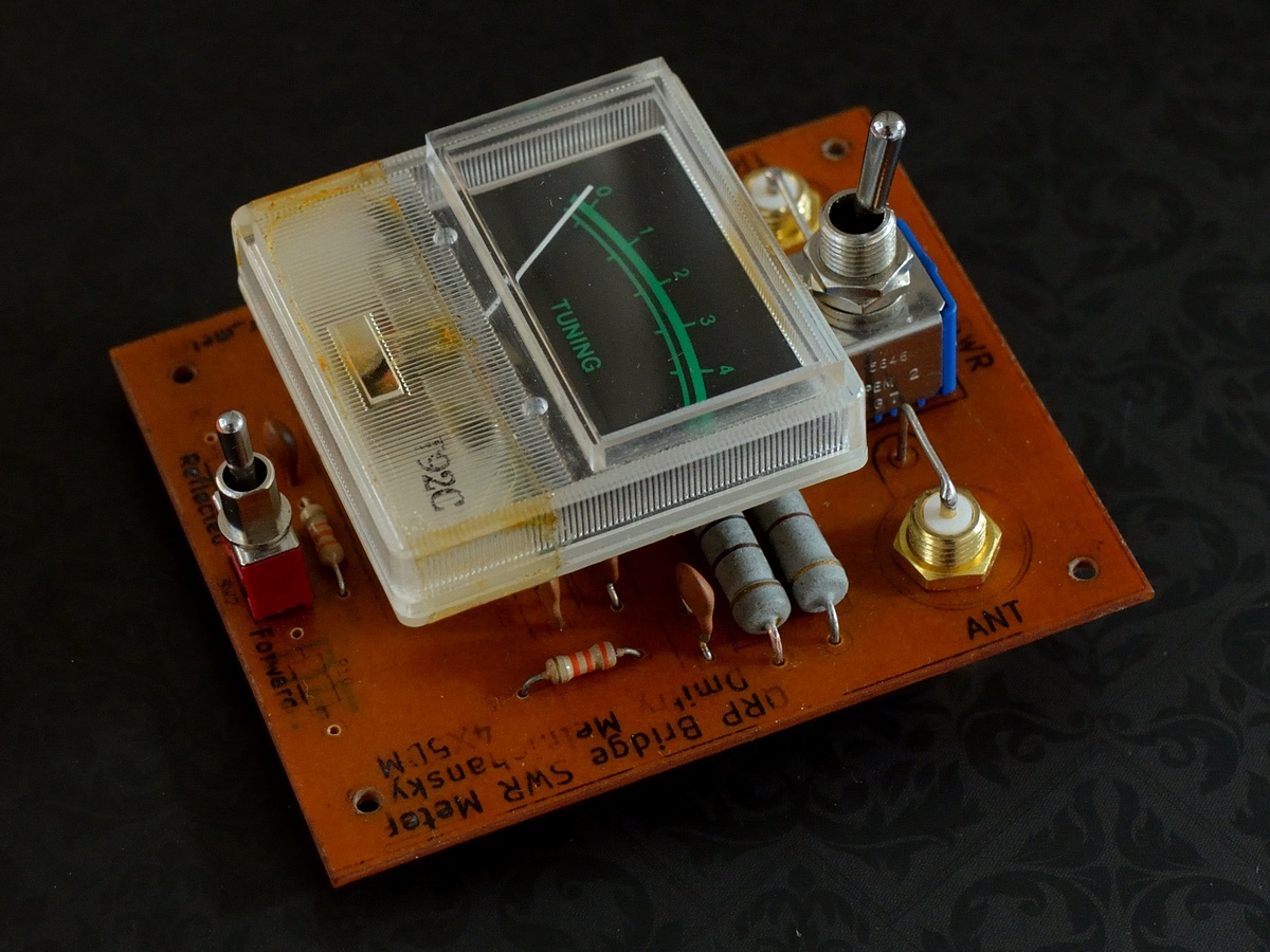
The microampermeter I used for SWR indication is actually a tuning indicator from an old radio receiver. Its full deflection current is 250uA and internal resistance is about 1.2K. These values are not critical and almost any microampermeter.
Circuit alignment showed that more critical parts are diodes. The first diodes I used were BAT49 Schottky diodes. Later, due to their high capacity I had to replace them with germanium 1N60P.
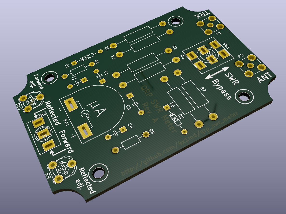
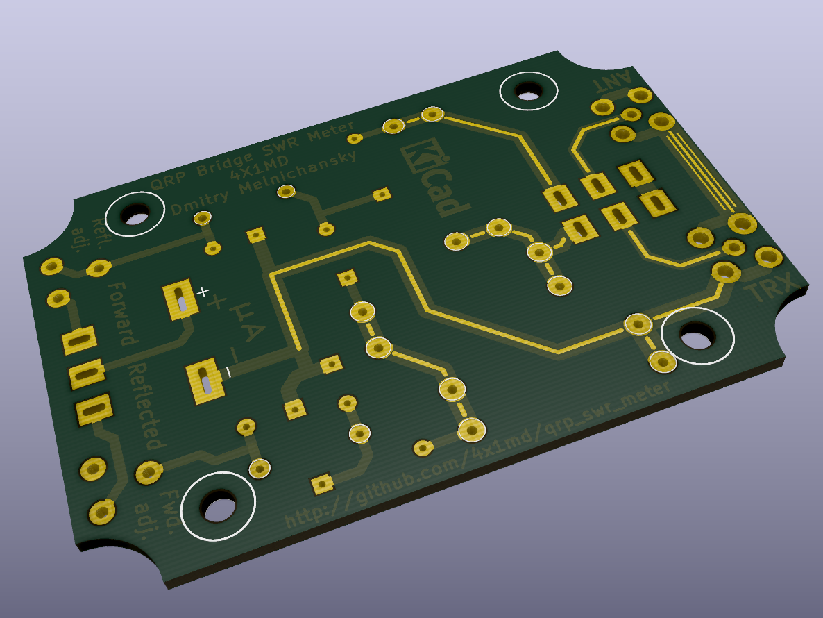
The PCB was designed using KiCAD software.
The first prototype was build on a random size PCB designed in KiCad Eschema. It used through hole mounted SMA female connectors.
At first, its performance was constantly starting to deteriorate at frequencies of 12-13MHz and higher. The investigation showed two main reasons:
- I didn't clean well the PCB after soldering and the remaining flux caused current leakage at higher frequencies.
- I used diodes with high capacity (more than 100pF).
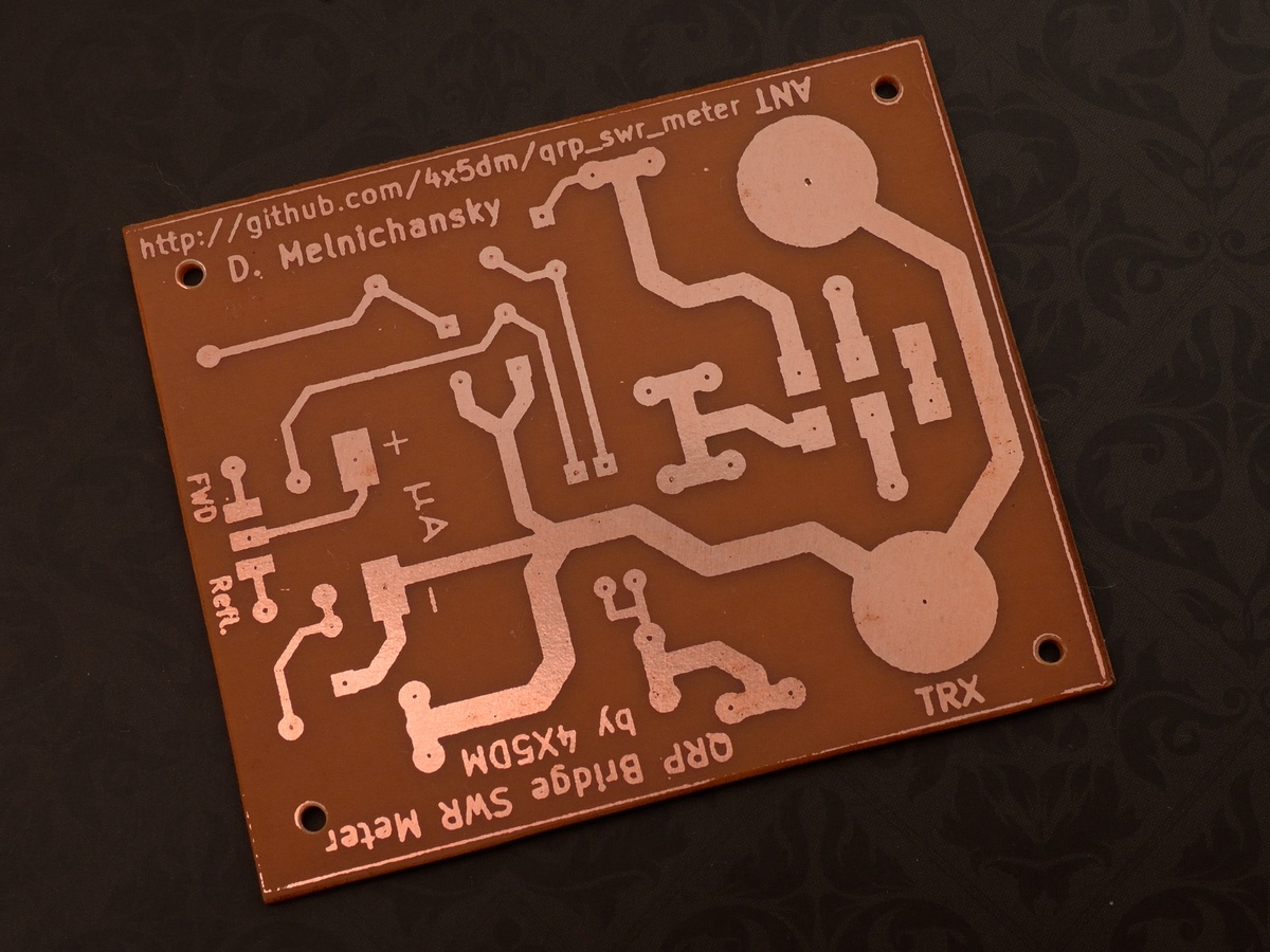
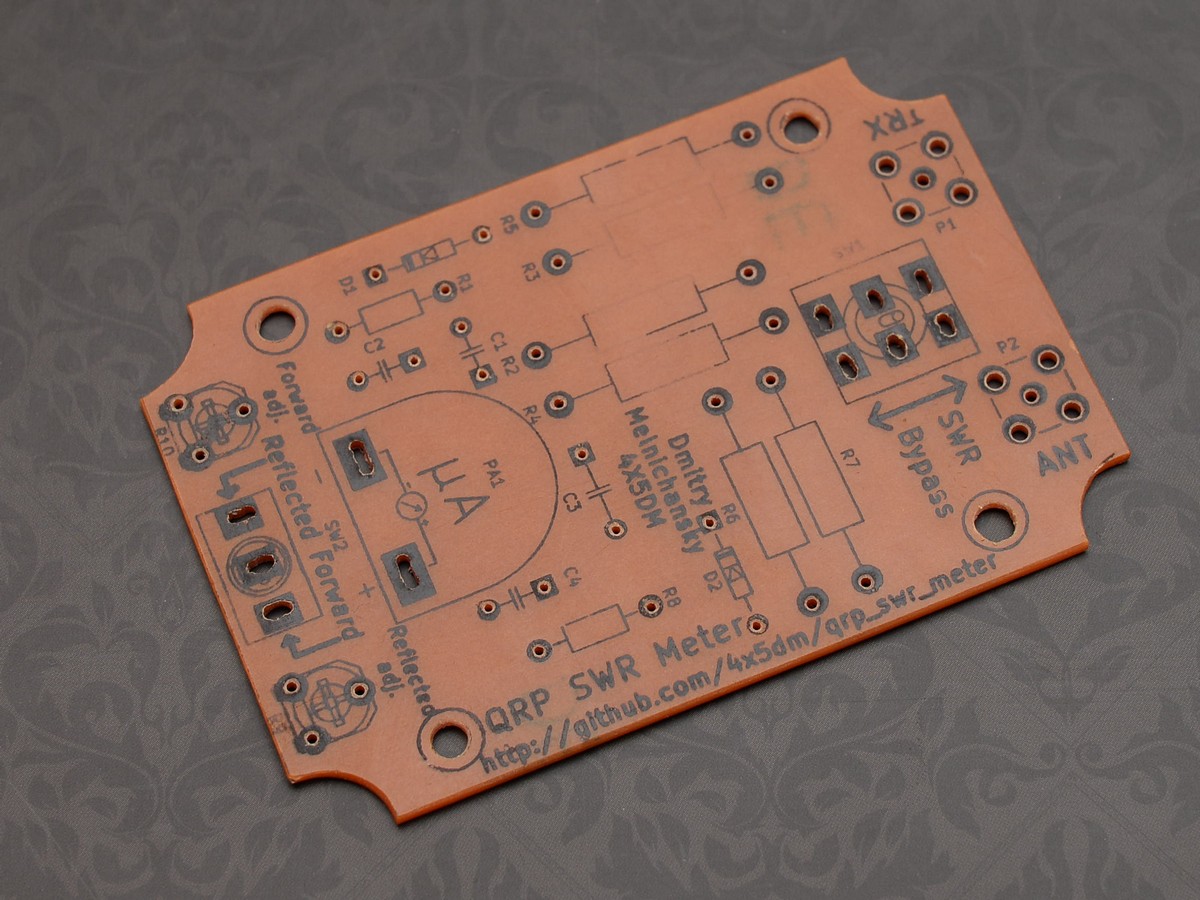
The PCB was made at home using toner transfer method.
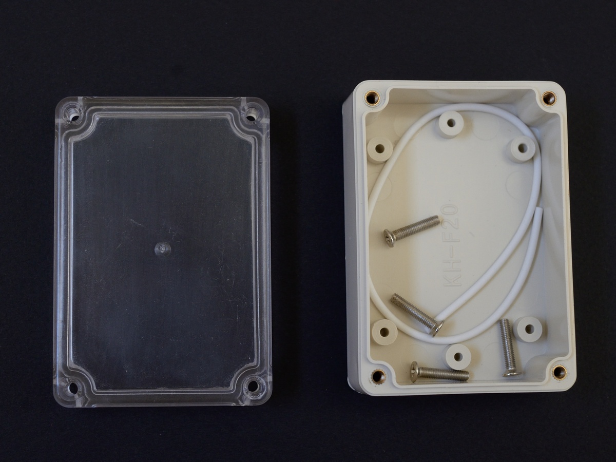
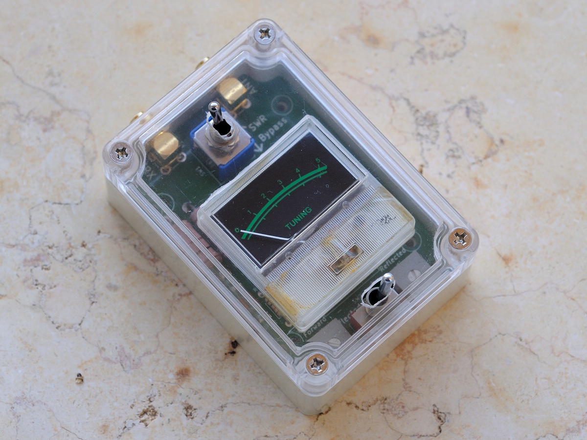
After getting the previous prototype to work well, I decided to put the device in an enclosure box. For that matter I chose a 83x58x35mm plastic box with transparent cover which is sold cheap on AliExpress.
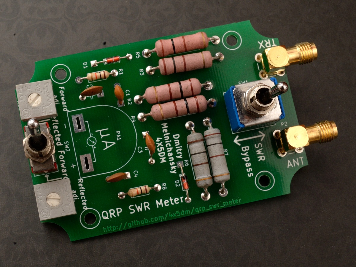
I had to redesign the PCB to match the inner dimensions of the box. I also decided to use right angle SMA connectors in this design. As a result I got the following prototype.
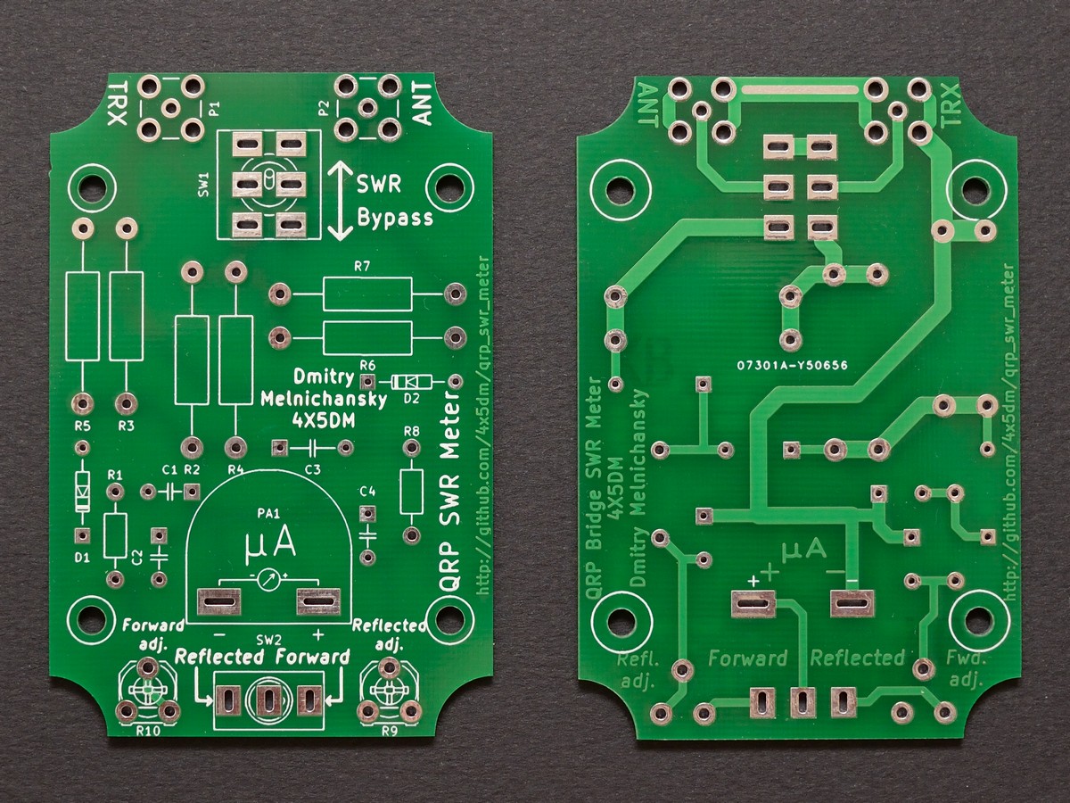
Later I decided to try to order a factory produced PCB. I ordered a small quantity from ITEAD Studio. As to my taste, they did a great job.
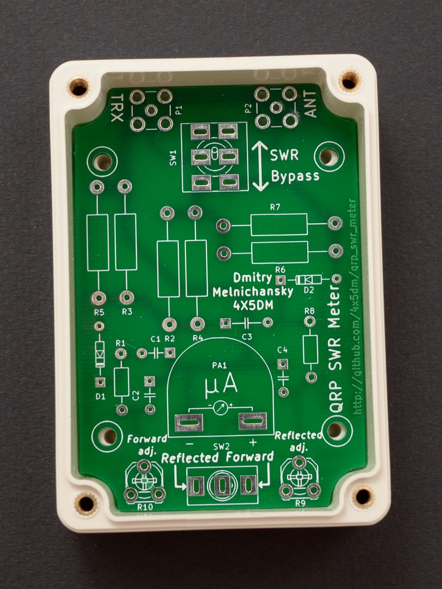
The board fits the box perfectly.
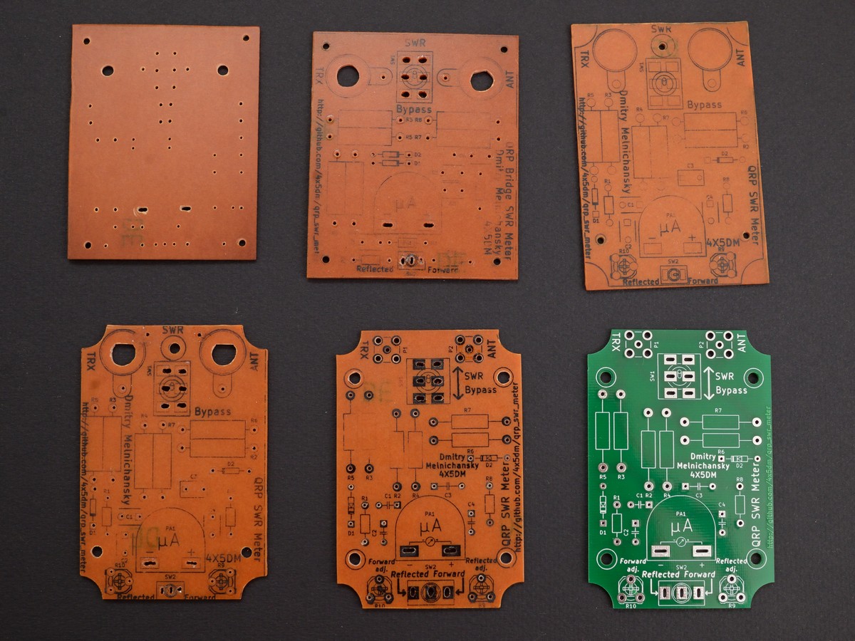
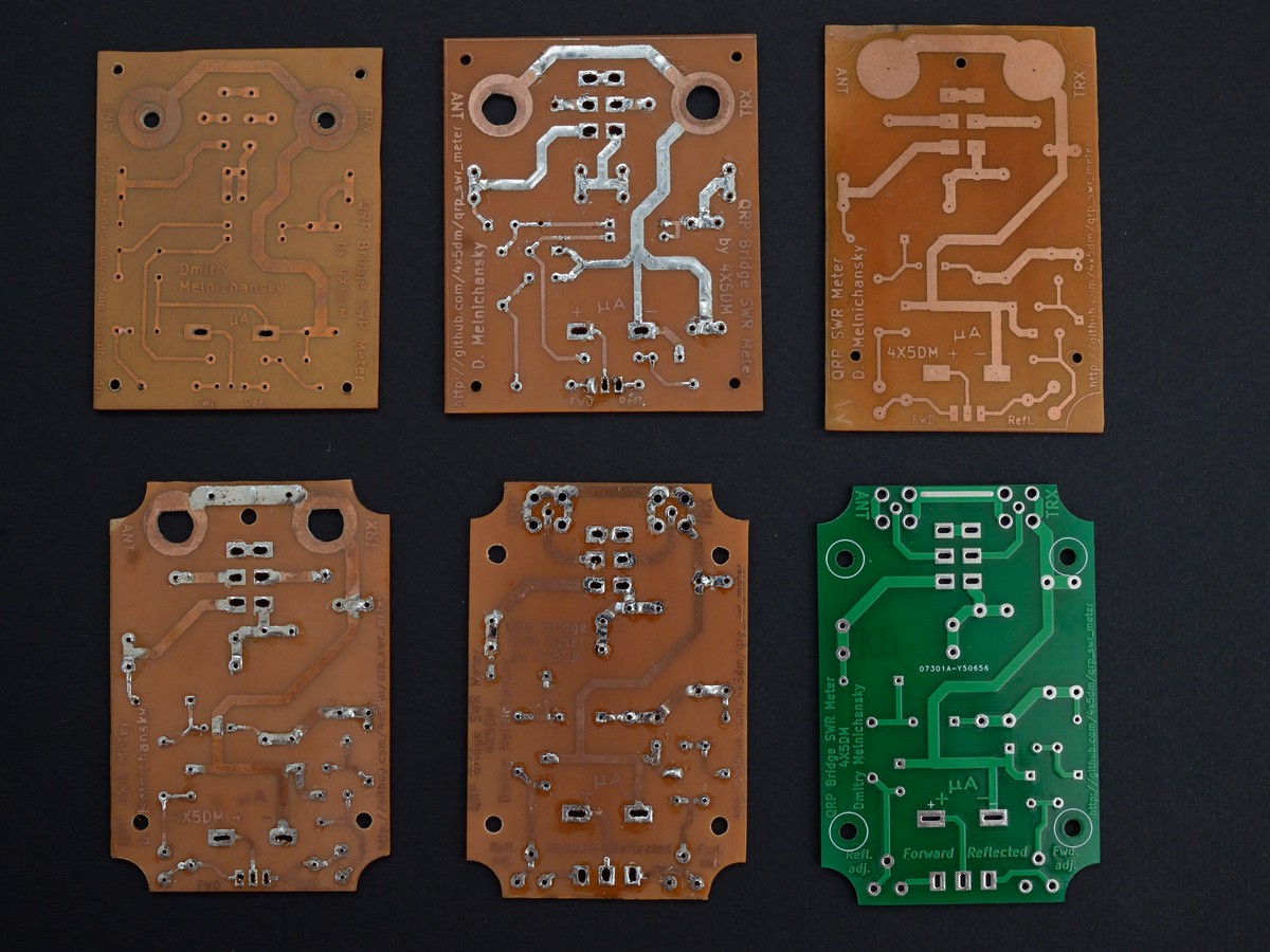
All my home-made PCB prototypes in two photos.
- Wideband SWR meter by Manfred Mornhinweg XQ6FOD (circuit 1)
- Circuit 2
- Circuit 3
- Circuit 4
- Measurements on Balanced Lines Using the Noise Bridge & SWR Meter by Lloyd Butler VK5BR. Amateur Radio, July 1992
- Low-power antenna tuner and SWR meter
- Simple LED SWR bridge by John Young G0WGR
- Измеритель КСВ by LY3BG
- КСВ-метры: теория и практика. Как сделать достоверный КСВ-метр by UT1MA
- Cheap and Easy Toner Transfer for PCB Making
- Easy, Consistent & Cheap Toner Transfer Method for Single & Double Sided PCBs
You are more than welcome to contact me with any questions, suggestions or propositions regarding this project. You can:
- Visit my QRZ.COM page
- Visit my Facebook profile
- Write me an email to iosaaris =at= gmail dot com
If you like this project, or found here some useful information and want to say thanks, or encourage me to do more, you can buy me a coffee!
You can aslo make a donation with PayPal:
73 de 4X1MD ex 4X5DM
