How to get a CAN connection between 2 or more BBBs
- 2x CAN transceiver breakout boards
- 1x breadboard
- 12x jumper leads or cables
- 2x BBBs
- 2x USB mini B cables
- 1x signal generator for testing
Connect 3.3V and ground on each transceiver to power supply/3.3v pins on BBB, power supply is better.
Then connect CANH to CANH, and CANL to CANL across the transceivers.
The transceiver at either end of the bus should have a 120 Ohm resistor bridging CANH and CANL, this is on the breakout board.
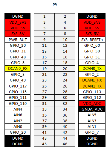
Connect CTX to a BBB using pin 9.26, and CRX to the same BBB using pin 9.24. Repeat with other BBB and transceiver.
Test that there are correct terminating resistors, detach breadboard from the power supply and check the resistance between CANH and CANL, it should read 60 Ohms. If it reads higher, one of the terminating resistors is missing. If it reads lower, this is likely due to using more than 2 transceivers with the non terminal nodes also having the terminating resistors.
Test that the transceivers produce the correct voltage with power. Attach to 3.3V power supply/BBB pins, and measure the voltage between CANH and ground, and CANL and ground. These should both be around 2.2V. If it doesn't, you have likely mixed up some leads, check all of them and ask someone else to check them too if possible. If there is no voltage, make sure the power supply is switched on.
Test that the transceivers correctly produce a differential. Set a signal generator to produce a 4v amplitude square wave, with an offset of 2 volts and a frequency of 10kHz. Probe CANH and CANL using an oscilloscope. CANH should alternate between ~2.2v and ~3.3v at 10kHz, with CANH being at 3.3v when the input is at 0v. CANL should alternate between ~1v and ~2.2v, with CANL being at 1v when the input is at 0v. If there is not a correct differential being produced, this is likely due to an incorrect lead, check all of them again. If this is correct, the power supply and signal generator are on, then there may be an issue with the transceiver chip itself. Replace the transceiver and repeat all tests again.
On both BBBs, enable the pins using config-pin p9.24 can and config-pin p9.26 can.
Then, enable the CAN interface using sudo /sbin/ip link set can1 up type can bitrate 10000.
Here is a bash script that will quickly perform the above:
#!/usr/bin/env bash


if [[ $# != 1 ]]; then
  echo "Provide 1 argument for bitrate"
  exit 1
fi

config-pin p9.19 can
config-pin p9.20 can
config-pin p9.24 can
config-pin p9.26 can
echo "Enabled CAN on pins p9.19, p9.20, p9.24, p9.26"

sudo /sbin/ip link set can0 down
sudo /sbin/ip link set can1 down
sudo /sbin/ip link set can0 up type can bitrate $1
sudo /sbin/ip link set can1 up type can bitrate $1
echo "Started can interfaces can0 and can1 with bitrate $1"
Now, run ifconfig. You should see CAN1 as one of the results.
Now that the hardware is set up, verified, and configured, you can send test messages using cansend, cangen, and candump.
On one BBB, run candump can1. This will output all received can messages to the terminal.
Probe CANH and CANL using an oscilloscope. Set the trigger appropriately and press the single button. This will freeze the scope as soon as a frame gets sent.
On the other BBB, run cansend can1 5A1#11.2233.44556677.88. This will send a can frame over the bus with ID 5A1, and data 1122334455667788. Any data and ID can be chosen, with ID being a 3 digit hex value, and data being up to 8 bytes. Data must be in full bytes, IE an even number of hex digits.
You should see the output in candump on the first BBB and the frame on the oscilloscope.
Once you have successfully transmitted a message, run sudo /sbin/ip link set can1 down then sudo /sbin/ip link set can1 up type can bitrate 500000 on both BBBs. This will set the bitrate of the can connection to 500kHz.
cangen can1 can be used instead of cansend. This will generate continual random can messages. It can take arguements such as -g 1, which would set the gap between frames to 1ms, or -n 100 which will send 100 frames, by default it will continue until the process is terminated or the cansend mailbox fills up. The mailbox will not fill up unless the bus is being filled by other nodes sending, or if there are no other BBBs on the bus, as it will keep resending the first message until it gets an acknowledgement. If the mailbox is full, run sudo /sbin/ip link set can1 down then sudo /sbin/ip link set can1 up type can bitrate 500000 on both BBBs to reset the connection, then ensure both BBBs are correctly set up before trying another send.
To be completed
When using more than 2 transceivers on 1 CAN bus, only the terminating transceivers should have the 120 Ohm resistors. Any other transceivers on the bus should not have this resistor, which would have to be de-soldered from the breakout board.