-
-
Notifications
You must be signed in to change notification settings - Fork 82
Troubleshooting
Schematics for the RaSCSI are available here: https://github.com/akuker/RASCSI/raw/master/hw/rascsi_2p3/rascsi_2p3_sch.pdf
First step in troubleshooting is to check the termination. Seriously. Check this.
https://lowendmac.com/1998/termination-explained/
Re-check it again.
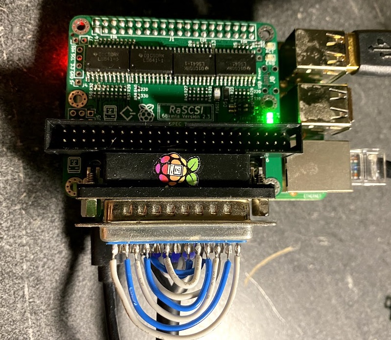
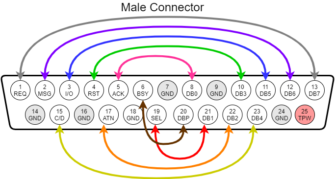
A way to check out the RaSCSI hardware is to create a loopback cable. This can be done using jumper wires or a specially-constructed DB25 male jack connector can be created to allow easy re-use.


The diagram for the loopback connections is shown here. Note that the RaSCSI connector is a FEMALE connector. If you are using a gender changer (as in the previous picture), you want to use the MALE connector pinout
FEMALE connector pinout 
|
MALE connector pinout 
|
Once you have the loopback connections made, you can checkout the RaSCSI source code and run the loopback test python script. (Note: This requires python3 to run)
Before running this test:
- Ensure that you have termination enabled before running this test!!
- Ensure that the RaSCSI service is NOT running `sudo systemctl stop rascsi`
- Double check your loopback that you do NOT have TERM POWER connected to Ground!!!

cd ~
git clone https://github.com/akuker/RASCSI.git
cd ~/RASCSI
# FOR NOW, the code is only available on the 'develop' branch
git checkout develop
cd ~/RASCSI/src/loopback_test/
pip install RPi.GPIO
./test.py
The Python test script will list all of the SCSI signals that are not working properly. You can the use the schematicto debug if there are any broken traces, lifted pads or bad solder joints.
Note: this concept was original created by Saybur for the Scuznet board: https://github.com/saybur/scuznet/tree/master/testing


In this case, there is something wrong with either the "C/D" SCSI signal or the "D4" SCSI data line or both.
You can test each individual SCSI signal using a multimeter. This procedure is listed here.
Turn on the termination DIP switches
Pull out your trusty multimeter. With the RaSCSI software running, disconnect all SCSI devices and check the voltages:
- TPWR should be 5v
- D0-D7 should be around 3.08v
- Control signals should be around 3.08v
- Check the LEDS
 raspi-gpio set 4 op dh #  ACT LED should be ON
 raspi-gpio set 4 op dl #  ACT LED should be OFF
 raspi-gpio set 5 op dh #  ENB LED should be ON
 raspi-gpio set 5 op dl #  ENB LED should be OFF
- Set the direction of the transceivers to be outputs
 raspi-gpio set 8 op dl #PI-DTD is GPIO 8 - set LOW for Pi->SCSI output
 raspi-gpio set 6 op dh #PI-IND is GPIO 6 - set HIGH for Pi->SCSI output
 raspi-gpio set 7 op dh #PI-TAD is GPIO 7 - set HIGH for Pi-SCSI output
- Check Data 0
 raspi-gpio set 10 op dh # D0 output should be around 3v
 raspi-gpio set 10 op dl # D0 output should be around 0v
- Repeat for all of the other data and control signals
 raspi-gpio set <GPIO> op dh # <Signal> output should be around 3v
 raspi-gpio set <Signal> op dl # <Signal> output should be around 0v
| Signal | GPIO | Direction Control | Direction: Pi->SCSI | Direction: SCSI->PI |
| D0 | 10 | DTD (GPIO 8) |
raspi-gpio set 8 op dl
|
raspi-gpio set 8 op dh
|
| D1 | 11 | DTD (GPIO 8) |
raspi-gpio set 8 op dl
|
raspi-gpio set 8 op dh
|
| D2 | 12 | DTD (GPIO 8) |
raspi-gpio set 8 op dl
|
raspi-gpio set 8 op dh
|
| D3 | 13 | DTD (GPIO 8) |
raspi-gpio set 8 op dl
|
raspi-gpio set 8 op dh
|
| D4 | 14 | DTD (GPIO 8) |
raspi-gpio set 8 op dl
|
raspi-gpio set 8 op dh
|
| D5 | 15 | DTD (GPIO 8) |
raspi-gpio set 8 op dl
|
raspi-gpio set 8 op dh
|
| D6 | 16 | DTD (GPIO 8) |
raspi-gpio set 8 op dl
|
raspi-gpio set 8 op dh
|
| D7 | 17 | DTD (GPIO 8) |
raspi-gpio set 8 op dl
|
raspi-gpio set 8 op dh
|
| DP | 18 | DTD (GPIO 8) |
raspi-gpio set 8 op dl
|
raspi-gpio set 8 op dh
|
| I/O | 25 | TAD (GPIO 7) |
raspi-gpio set 7 op dh
|
raspi-gpio set 7 op dl
|
| REQ | 22 | TAD (GPIO 7) |
raspi-gpio set 7 op dh
|
raspi-gpio set 7 op dl
|
| C/D | 24 | TAD (GPIO 7) |
raspi-gpio set 7 op dh
|
raspi-gpio set 7 op dl
|
| MSG | 23 | TAD (GPIO 7) |
raspi-gpio set 7 op dh
|
raspi-gpio set 7 op dl
|
| BSY | 26 | TAD (GPIO 7) |
raspi-gpio set 7 op dh
|
raspi-gpio set 7 op dl
|
| SEL | 27 | IND (GPIO 6) |
raspi-gpio set 6 op dh
|
raspi-gpio set 6 op dl
|
| RST | 20 | IND (GPIO 6) |
raspi-gpio set 6 op dh
|
raspi-gpio set 6 op dl
|
| ACK | 21 | IND (GPIO 6) |
raspi-gpio set 6 op dh
|
raspi-gpio set 6 op dl
|
| ATN | 19 | IND (GPIO 6) |
raspi-gpio set 6 op dh
|
raspi-gpio set 6 op dl
|
This is a known bug with the RaSCSI software. You can mitigate it by changing IDs around.
- For example,
 ID 1 - RaSCSI-Boot.hda
 ID 2 - DaynaPort SCSI/Link
- would become
 ID 0 - RaSCSI-Boot.hda
 ID 1 - DaynaPort SCSI/Link
This bug will be fixed in a future update. I've seen the most success attaching the DaynaPort on ID 1, as ID 2 gave me the Duplicate ID error. This only seems to be happening with the DaynaPort device.
If you see an error like the following, your Raspberry Pi OS may be too old.
log.h:22:3: error: ‘log’ is not a member of ‘spdlog’
   spdlog::log(loglevel,buf);}while(0);
The easiest approach would be to generate a new SD card with the latest version of Raspberry Pi OS, using the Raspberry Pi Imager (https://www.raspberrypi.org/software/). You can also try to update libspdlog-dev to a newer version.
You can check which version of spdlog you're using with the following command:
pi@rascsi:~ $ sudo apt search libspdlog
Sorting... Done
Full Text Search... Done
libspdlog-dev/stable,now 1:1.3.1-1+rpi1 armhf [installed]
  Very fast, header only, C++ logging library

pi@rascsi:~ $- Home
- Initial Setup
- Documentation
- Companion Apps
- Developer Notes