Mifare Classic 1k and 4k dumps parser in human readable format.
Dumps can be grabbed with mfterm, mfoc or nfc-mfclassic tools from libnfc.org
Dump file size must be 1024 or 4096 bytes.
Also try this https://github.com/asdil12/mifare-view-dump
Included dump.mfd -- Mifare 4k dump for testing.
easy_install bitstring
or
pip install bitstring
mfdread.py ./dump.mfd
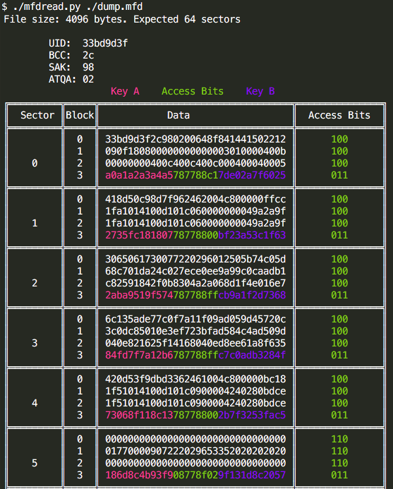
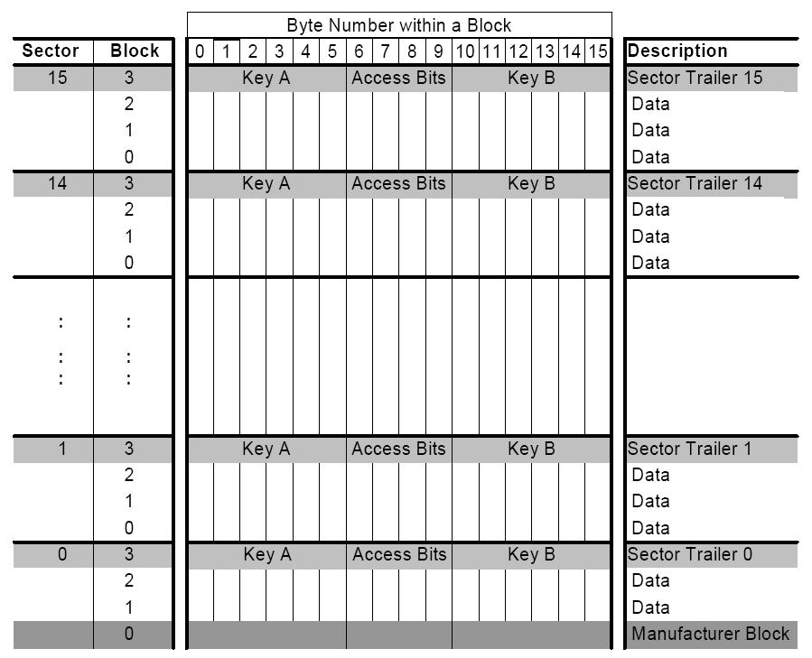
The total memory of 1024 bytes in Mifare Classic (1k) and 4096 bytes in Mifare 4k is divided into 16 sectors of 64 bytes, each of the sectors is divided into 4 blocks of 16 bytes. Blocks 0, 1 and 2 of each sector can store data and block 3 is used to store keys and access bits (the exception is the ‘Manufacturer Block’ which can not store data).
The memory of 1KB and 4KB MIFARE Classic cards is ordered in a similar way. On both cards the first block (block 0) contains the UID, BCC, SAK, ATQA and Manufacturer data. This block is locked and cannot be altered. But some times it can be ;)
Access bits define the way the data in the sector trailer and the data blocks can be accessed. Access bits are stored twice – inverted and non-inverted in the sector trailer as shown in the images.
Some examples:
Data stored in the sector trailer:
01 02 03 04 05 06 FF 07 80 69 11 12 13 14 15 16
01 02 03 04 05 06 – Key A
FF 07 80 69 – Access bits
11 12 13 14 15 16 – Key B (or data if Key B is not used)
Bytes 6, 7, 8 are access data
FF 07 80
Binary representation:
11111111 = FF
(0)0000111 = 07
**(1)000(0)**000 = 80
The bits that are bolded and in parentheses are the ones that define access to keys (C13, C23, C33 in the image above) and they form the 001 sequence. The bits that are bolded and not in parentheses are the same bits inverted. They form, as expected, the sequence 110.
From the table above I can see that 001 means that Key A can not be read, but can be written and Key B may be read. This is the "transport configuration" and was read from the card that was never used.
Another example where access bits 6,7,8 are 0x78 0x77 0x88

| Abbreviation | Meaning |
|---|---|
| UID | Unique Identifier, Type A |
| NUID | Non-Unique Identifier |
| ATQA | Answer To Request acc. to ISO/IEC 14443-4 |
| SAK | Select Acknowledge, Type A |
| ATS | Answer To Select acc. to ISO/IEC 14443-4 |
| ATR | Anser To Reset What's really ATR means |
| APDU | Application Protocol Data Unit |
| DIF | Dual Interface (cards) |
| COS | Card Operating System |
| CL | Cascade Level acc. to ISO/IEC 14443-3 |
| CT | Cascade Tag, Type A |
| NFC | Near Field Communication |
| PCD | Proximity Coupling Device (“Contactless Reader”) |
| PICC | Proximity Integrated Circuit (“Contactless Card”) |
| PKE | Public Key Encryption (like RSA or ECC) |
| REQA | Request Command, Type A |
| Select | Select Command, Type A |
| RID | Random ID, typically dynamically generated at Power-on Reset (UID0 = “0x08”, Random number in UID1… UID3) |
| RFU | Reserved for future use |
ATR is for contact cards and is specified in ISO 7816. For contacless cards, it is the PC/SC reader (IFD) that generates the ATR.
The ATR is constructed based on:
ATS (Answer to Select) for ISO 14443 Type A cards ATQB and ATTRIB bytes for ISO 14443 Type B cards The ATR will be of the form 3B 8X 80 01 HB_ATS Parity_Byte where X is the number of bytes of Historical Bytes of ATS (HB_ATS).
The exact construction of ATR for contactless cards is given in section 3.1.3.2.3 of the PC/SC spec.
Given that the only variable is ATS, it should be the same regardless of the reader.