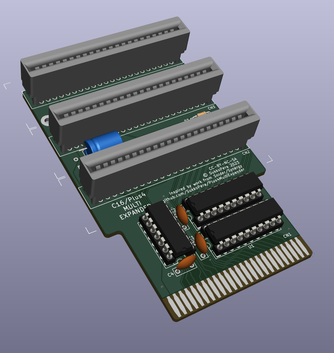
Plus4MultiExpander is a port expander that allows multiple boards to be connected to the Expansion port of a Commodore 16, 116 and Plus/4.
The main problem in making an Expansion port extender for the 264 line of computers is the complete unavailability of the original connector: these machines use a 50-pin connector with 2.00 mm pitch, which is nowhere to be found. This has been a problem since the old days, as you can see that even Solder of Synergy used different connectors when he made his Expansion Port Splitter in 1994. He used 50-pin connectors with 2.54 mm pitch, which in turn became rather uncommon in the following years, until they recently resurfaced from Chinese sellers.
This problem with the unavailability of the connector also affects LittleSixteen. Since one of the goals of that project is to fit into an unmodified C64-style case, Solder's connector of choice wouldn't help, as it is much larger than the opening on the case.
Of course, the opening on the case was made for the 44-pin 2.54 mm pitch connector the C64 uses, which for some reason is still available on the market, even from reliable manufacturers. It only has 6 pins less and since some of the pins on the 264 line are not used, I decided it was the best candidate for the new Expansion connector of the 264 line of computers.
Significant inspiration for the design of the expander comes from Solder's 1994 version. In particular, the expander integrates buffers for the address bus, in order to compensate for the increased bus capacitance. No buffers seem to be required on the data bus.
As mentioned, 50-44=6 pins need to be dropped from the original connector:
- 3 are obvious, the unused pins: Z, AA, BB
- Since it is basically impossible to make an external RAM expansion, two more obvious drops would be the pins for the
/RASand/CASsignals. Unfortunately,/RASis used by the 1551 drive paddle to (re)generatePHI2, but I see no reason for that, asPHI2is directly available on the connector. However, this is not enough of a reason to keep those signals: since in any case we will need to design a replacement paddle PCB with the new connector, we can also make it use that signal directly (This was even already done, as TCBM2SD can work as a 1551 paddle replacement and it doesn't need/RAS). - For the remaining pin, even if
MUXseems to only make sense for RAM expansions, it cannot be dropped since it is used as a clock signal by SIDcards (and by my upcoming DigiMoooZ as well). - After a long research, I rather decided to merge
/C2_LOand/C2_HIinto a single signal which I dubbed/C2. This seemed the best choice for a number or reasons:- Those signals are rarely used (I only know of one cartridge needing them).
- When they are needed, they can sometimes be replaced by the new
/C2signal. - If absolutely necessary, the original signals can be perfectly recreated very easily (see below).
- While the same approach could be applied to the
/C1_LOand/C1_HIsignals in order to spare yet one more pin, I opted not to do it, since these are much more frequently used and would require extra logic on every cartridge using them.
Very simply:
/C2 = /C2_LO and /C2_HI
This requires a simple AND gate (I used a common 74HCT08 logic chip to do that, whose spare gates were used to "buffer" some other signals). The original signals can be reconstructed as follows:
/C2_LO = /C2 or /CS0
/C2_HI = /C2 or /CS1
Another decision I had to take was whether to leave the signals in the +4 order or reorder them in C64 style: since now a C64 cartridge can be physically connected to a +4, I thought it would be appropriate to put some effort into making that a bit safer from the electrical point of view, so I went with the reordering.
That left only three pins with possible conflicts:
- Pin 13 outputs
MUX, while on the C64 it is an input for/DMA. - Pin 8 outputs
AEC, while on the C64 it is an input for/GAME. - Pin D outputs the new
/C2signal, but on the C64 this pin is an input for the/NMIsignal.
Therefore, the current board is not completely safe in this regard, so never plug a C64 cartridge into the expander. In a future version series resistors might be added to prevent any mishaps.
Since multiple audio cards might be plugged into the expander, sending their outputs to the AUDIO_IN pin, I added a passive mixer circuit to the expander.
This is constituted by resistors R1/R2/R3 and unfortunately it might have the side effect of lowering the output volume. To avoid this, you can enable sound output on a single connector: just mount a single 0 ohm resistor depending on which slot you want to enable: R1 for CN2, R2 for CN3 and R3 for CN4.
The board has been made as large as possible while still being cheap to manufacture (which implies a maximum size of 10x10 cm). I wanted to fit at least 3 connectors and the spacing among them should be enough for standard-size cartridges.
If you have thicker cartridges, try putting them in the first or last slot, where you can probably gain some space by bending them slightly, or remove them from the case. Good-quality connectors will have no problems keeping them straight.
Of course, feel free to fork the project and make a larger version and/or with more connectors.
I recommend mounting standoffs to keep the board straight: holes accept M2 screws and the recommended height is around 12 mm.
Of course, the new connector means losing compatibility with all the existing boards. While that might make the whole thing sound crazy, it is not as bad as it seems: in the past years I have redesigned most of the C16/+4 expansion boards that are still relevant, and released all of those with an open source license. Therefore, it is generally a quick and easy job to update them with the new connector and release 44-pin versions. I have already done it with the following:
I have also made a 44-pin version of ytmytm's TCBM2SD.
I will slowly port other projects to the new connector as I have a need for them, but feel free to send me a request if you want something particular to be done, or just fork the project and do it yourself! That's the whole point of open source stuff and, as I said, it is generally an easy job.
In line of principle, it is also possible to make adapters between the two connectors, but of course the old-to-new variant is subject to the unavailability of the 50-pin connector. Nevertheless, I had a go at it.
The LittleSixteen project is planned to adopt the 44-pin connector in V5.
If you want to get this board produced, you are recommended to get the latest release rather than the current git version, as the latter might be under development and is not guaranteed to be working.
Every release is accompanied by its Bill Of Materials (BOM) file and any relevant notes about it, which you are recommended to read carefully.
The Plus4MultiExpander documentation, including the design itself, is copyright © SukkoPera 2023 and is licensed under the Creative Commons Attribution-NonCommercial-ShareAlike 4.0 International License.
This documentation is distributed as is and WITHOUT ANY EXPRESS OR IMPLIED WARRANTIES whatsoever with respect to its functionality, operability or use, including, without limitation, any implied warranties OF MERCHANTABILITY, SATISFACTORY QUALITY, FITNESS FOR A PARTICULAR PURPOSE or infringement. We expressly disclaim any liability whatsoever for any direct, indirect, consequential, incidental or special damages, including, without limitation, lost revenues, lost profits, losses resulting from business interruption or loss of data, regardless of the form of action or legal theory under which the liability may be asserted, even if advised of the possibility or likelihood of such damages.
If you want to get some boards manufactured, you can get them from PCBWay through this link:

You get my gratitude and cheap, professionally-made and good quality PCBs, I get some credit that will help with this and other projects. You won't even have to worry about the various PCB options, it's all pre-configured for you!
Also, if you still have to register, you can use this link to get some bonus initial credit (and yield me some more).
You can also buy me a coffee if you want:
- Solder of Synergy for making the original splitter.
- Haegar of Synergy for help and assistance.