- Replace Power Connector
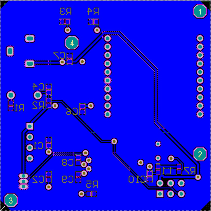
- Replace all SMT to 0603
- Digital Vcc Decoupling Capacitor
- Buck Converter
LM2576LM2596LM1117 - Analog Avcc Decoupling Capacitor
- Light Sensor
- Add PhotoCell
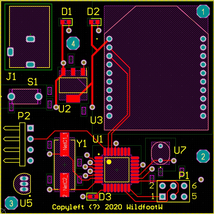
- Add Border on PCB
- Change DHT22 to Header
- Add Screw Hole
- Add Test LED
-
ATmega328P
-
XBee
-
DS18B20
-
DHT22
-
Power Supply
- AMS1117-3.3 over-heating and blow up way below max current
- 5V Voltage Regulator, LM7805 vs LM2940 vs LM1117 vs AMS1117
LM2576- Datasheet
- ELECTRICAL CHARACTERISTICS LM2576-3.3 - 6V ≤ VIN ≤ 40V, 0.5A ≤ ILOAD ≤ 3A
LM2596AMS1117- Datasheet
- Out of Stock
- LM1117

-
AVR® Microcontroller Hardware Design Considerations
- 2.1 Ditital Supply
- Put decoupling capacitors near IC
- For devices with multiple pairs of power and ground pins, it is essential that there is a decoupling capacitor for every pair of pins.
- 2.2 Analog Supply
- Avcc ensures the analog circuits are less prone to the digital noise
- AREF must also be decoupled. The typical value is 100 nF
- If a separate AGND is present, the ground should be separated from digital ground. (analog & digital grounds are connected only at power supply GND)
- 3 Connection of RESET Pin on AVR Devices
- The recommended pull-up resistor value is 4.7 kΩ (For DebugWIRE to function properly, the pull-up must not be less than 10 kΩ)
- Using an extra capacitor is an additional protection. (cannot be used when DebugWIRE or PDI is used)
- Recommend add an ESD protection diode (cannot work with HVPP). Alternatively, a Zener diode can be used to limit the Reset voltage relative to GND (highly recommended in noisy environments).
- 3.1 External RESET Switch
- It is important to add a series resistance (330R)
- 4.1 SPI Programming Interface
- A few ISP programmers are powered by the target power supply. In this way they easily adapt to the correct voltage level of the target board.
- Other ISP programmers, such as STK600, can alternatively power the target board via the VTG line. In such a case, it is important that the power supply on the target is not switched on.
- 2.1 Ditital Supply
-
Crystal Oscaillator 16MHz
- Table 8.3 - 12-22 pF
-
debugWIRE
-
Serial Interface
- Difference between 1206, 0805 and 0603 SMD resistor
-
If you need to hand solder them, I suggest not going too small,e specially if you do not have any experience. 0603 should be fine for almost everyone, 0805 even more so, 1206 is a huge beast you can solder with your hands tied and your eyes closed.
-
- 0603(0.06 inch * 0.03 inch) == 1608 (1.6 mm * 0.8 mm)