Home

This guide was made and is maintained by Alberto Rota. Contributes, issues and corrections are welcome at Alberto's email.
- Table of Contents
- Virtual Simulator Basics
- Requirements
- Installation
- STEP 1 - Power on the robot
- STEP 2 - Turn on the HRSVs
- STEP 4 - Start the ROS network
- STEP 5 - Launch the dVRK simulator console
- STEP 6 - Launch the ROSBridge Server and the STEVE-ROSPacakge
- STEP 7 - Launch Unity
- STEP 9 - Launch the simulator
- Commands and the User Interface
STEVE is the virtual surgical simulator of the daVinci robot at NEARLab. STEVE replicates the motion of the real robot inside a virtual environment, allowing for high customizability and safe testing. You interact the simulator in the same way you interact with the daVinci from the Surgical Cart: you'll see the virtual environment from the HRSVs instead of the endoscope feed.
STEVE has been tested on a Windows 11 x64 PC with an 11th Gen Intel Core i7 2.80Hz processor, 16GB of RAM and no dedicated graphics card. Other researchers with different operating systems and specs have used STEVE on their machine with a few (solved) compatibility issues. It should run on any computer with a similar or better configuration.
WE ARE CURRENTLY WORKING ON DEPLOYING STEVE ON A DEDICATED MACHINE AT NEARLAB-MRS
Following is the list of requirements to run STEVE on your computer:
Unity: Version 20.3.21f1
The simulator should run with no compatibility issues also on newer versions of Unity, but it has not been tested on those platforms. Therefore, using the version specified above is recommended, although it is not a strict requirement.
Ethernet Connection
The simulator requires the connection to the dVRK ROS network. At NearLab, this connection is wired-only for security reasons: plug the ROS ethernet cable into your computer. If your computer does not have an ethernet port, you need to use a USB-to-ethernet adapter
🌐 Amazon link
Blender
3D objects are rendered through the Blender engine. Install the newest version to properly display the 3D objects.
If you plan on working only on Unity and not on the ROS side of the project, you can skip the rest of the "Requirements" section
ROS: Melodic or Noetic
The simulator has been tested with ROS Melodic and Noetic. If you need to write custom nodes, echo on topics or use the ROS command line, you need to install ROS on your computer.
NOTE: ROS works only on Linux
- If you have a Windows PC: Install WSL, a command-line only Linux environment which runs inside windows,
- If you have a Mac: You’ll need to install a Virtual Machine, this video may help you
- If you have Linux PC: Make sure it’s 20.04 (Focal)
Rosbridge Server
Unity cannot read ROS messages by himself. In order to communicate with ROS, we need to use a bridge that translates ROS messages into a format that Unity can understand. The Rosbridge package makes this conversion possible
Download the latest stable release from the release page as a .unitypackage file.
Then, open Unity and create a new project in the folder of your choice. When the project is open, go to Assets > Import Package > Custom Package and select the .unitypackage file you just downloaded. Keep all the files selected and click Import.
It could take a while to import all the files. When the process is finished, you should see the model of the daVinci robot and a template surgical scene. Double-click on ROBOT in the hierarchy panel to see the virtual robot.
If you see no error messages in the Unity console and the robot is displayed correctly, you are ready to start the simulator.
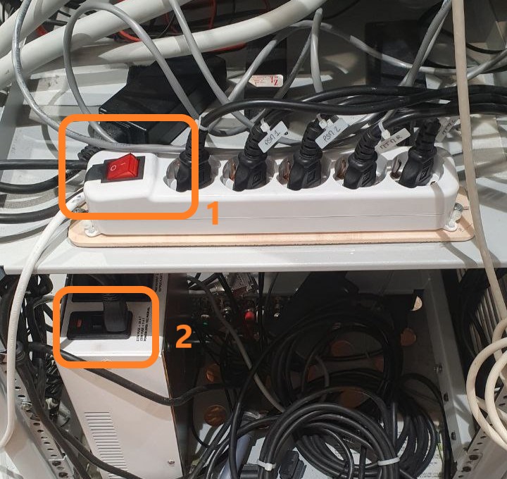
On the back of the Controller Cart, turn on the main power switch [1] and the endoscope power switch [2], as indicated in the figure
At the surgical console, no video should be displayed inside the binocular. To turn on these displays reach under the cart (see photo) and press the button on the piece of circuitry highlighted in orange in the pic. The button is not immediately reachable, but it's easy to find by touching the component.
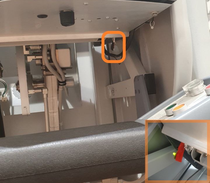
Once the button is pressed, an LED should turn on. The LED light is:
- OFF if the display is turned off
- ORANGE if the display is turned on but it's not connected to any video source
- GREEN if the display is turned on and connected to a video source
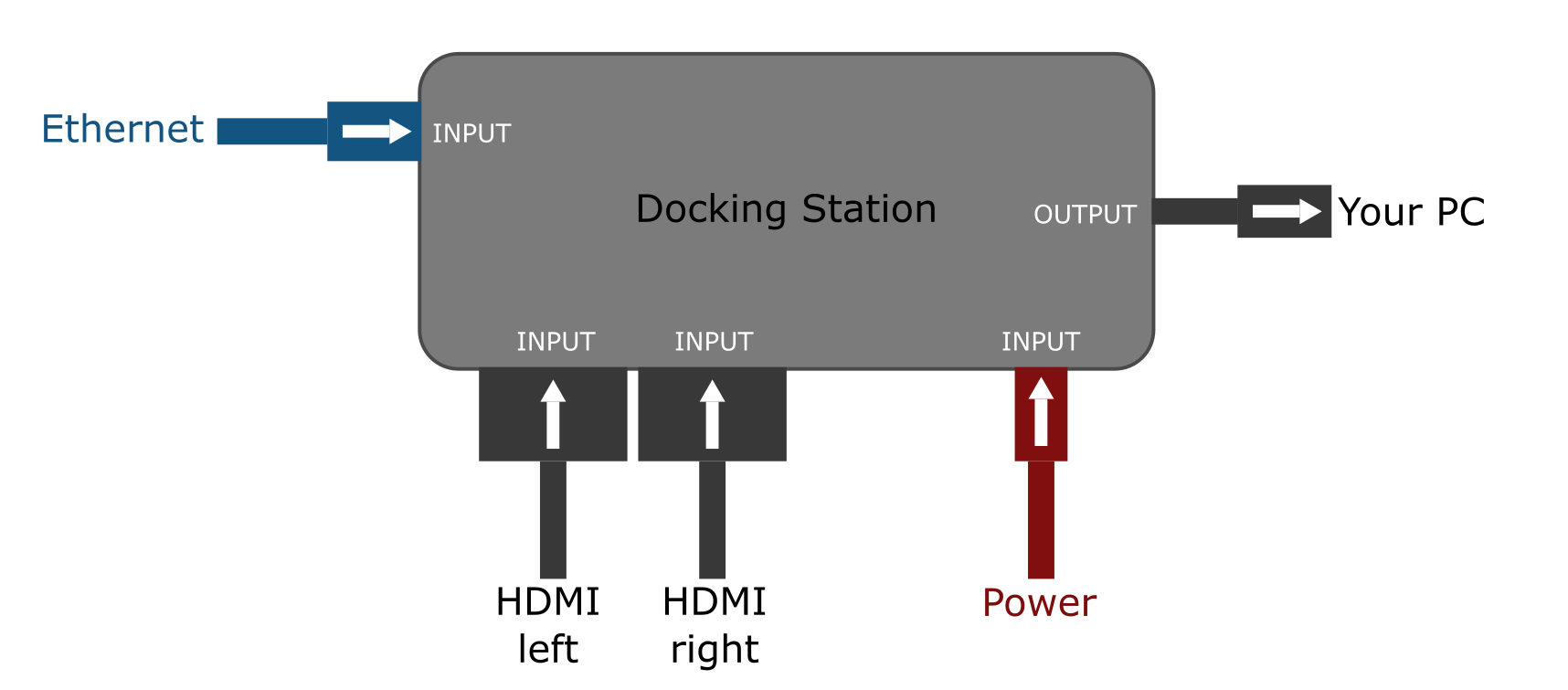
Each of the two HRSVs acts as a separate HDMI monitor and it will display as so into the display manager of your OS.
With the docking station available in the lab, connect your computer to the two HDMI cables (left and right) that input to the HRSV. The docking station should input the two HDMI signals, the Ethernet cable and the USB-C power cable, outputting a single USB-C cable to your computer.
NOTE: Although no problems has risen up till now, connect the power cable to the docking station and not to your PC. The docking station will share the power with your computer through the USB-C cable.
Your configuration should look like this:
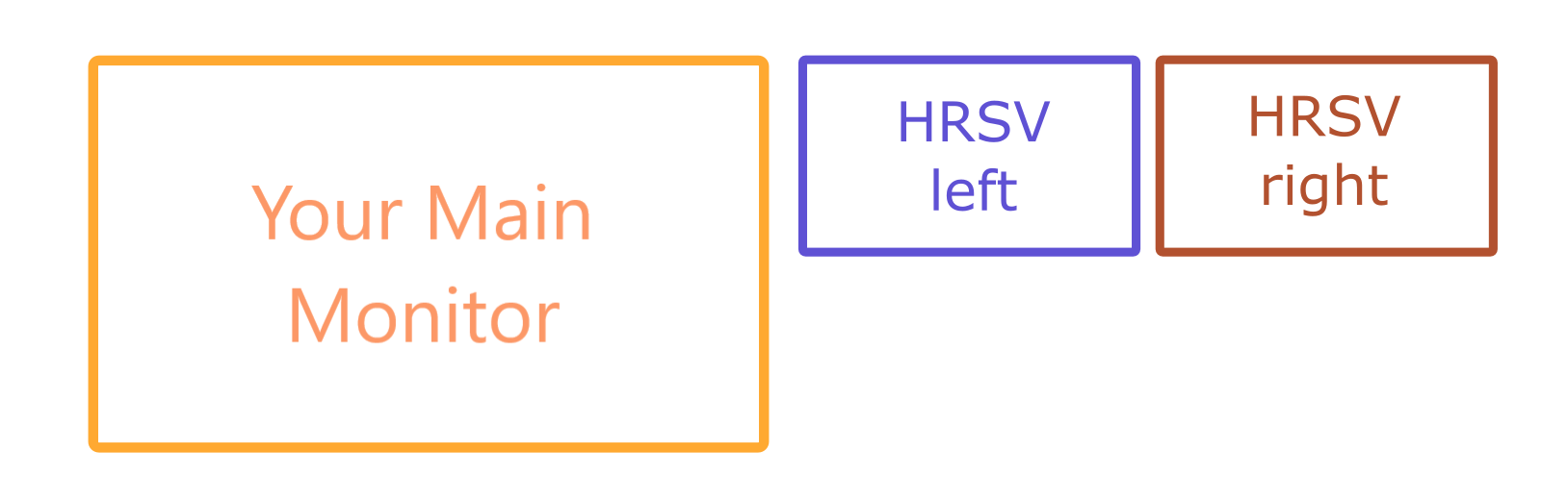
In the display settings of your computer, make sure that both monitors are connected and check in which position they have been placed. An example may be the following:
TROUBLESHOOTING: If, in the HRSV ocular, the message INPUT NOT SUPPORTED or FREQUENCY NOT SUPPORTED is displayed, check that the HDMI cables are properly connected to their adapter and to the docking station, and that the output resolution is set to 1920x1080 and the frequency to 60Hz.
Check that the LED below the console is green and that you can see your monitor (or your desktop wallpaper) in the oculars
On the GRU computer, open a terminal and (outside of the (base) conda virtual environment) start the ROSMASTER with
roscore
On the dVRK computer, open a terminal and launch the simulator console with
dvrk_simulator
This command sources the ROS environment, closes the safety relays for the QLA boards on the controller and opens the GUI control panel. In order to open the control panel, the previous two commands must be executed successfully.
The command outputs three yellow message, one for each function, and an OK confirmation or an ERROR message.
Most often, at startup, the QLA relay closing procedure will fail due to communication mismatches. In this case, you will see
> Sourcing devel/setup.bash >> OK
> Closing Safety relays >> ERROR
Check that the FireWire cable is connected to the dvrk PC. If t s, un-plug it and plug it
In that case, UNPLUG AND RE-PLUG THE FIREWIRE CABLE IN THE UNUSED PORT ON THE BACK OF THE dVRK COMPUTER.
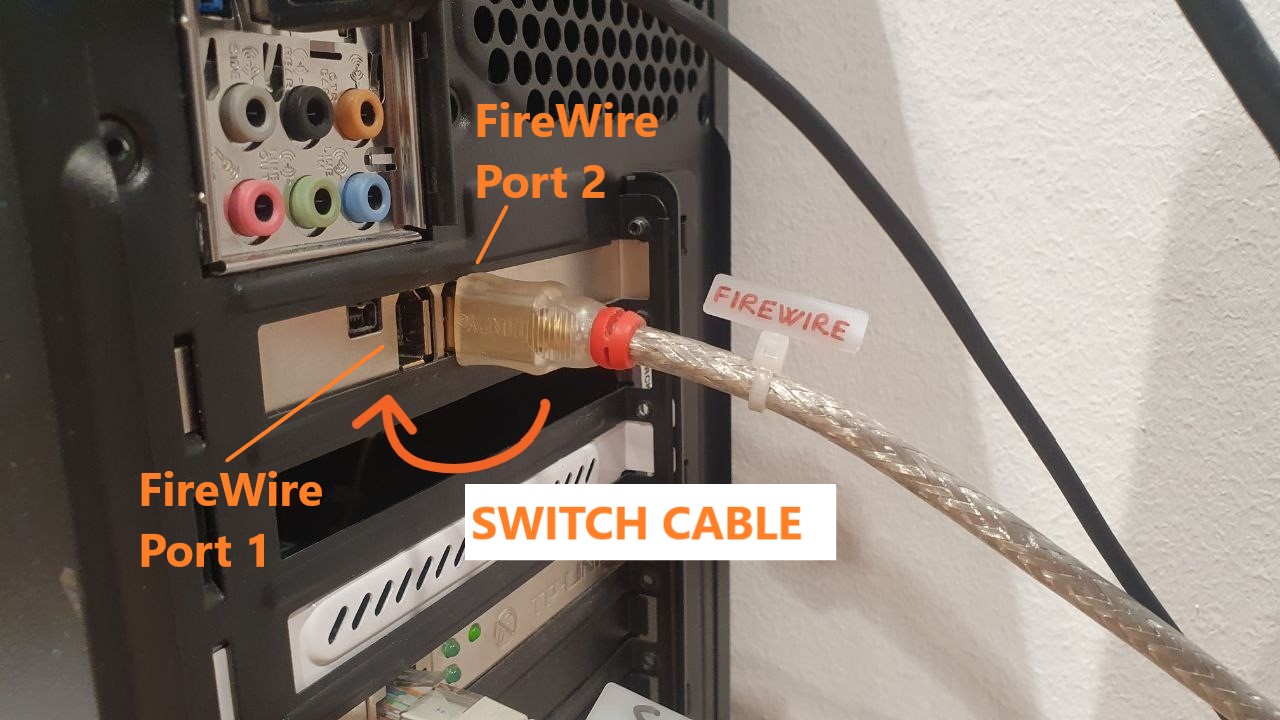
Please note that this MAY NOT WORK AT FIRST TRY. It is suggested to:
- Unplug the FireWire cable
- Pluge the FireWire cable in the adjacent port (the one where the cable was not plugged in)
- Test the
dvrk_teleoperationcommand - If you still get an error, unplug the FireWire cable and plug it in the original port
- Test the
dvrk_teleoperationcommand again - If you still get an error, repeat the procedure from step 1
- If after many tries you don't receive an OK message, check that all the previous STEPs have been executed correctly.
If the command is executed successfully, the following prompt will appear:
> Sourcing devel/setup.bash >>
OK
> Closing Safety relays >>
OK
> Launching dVRK GUI >>
CHECK OUTPUT
and a control panel similar to the one in the figure will appear after a few seconds.
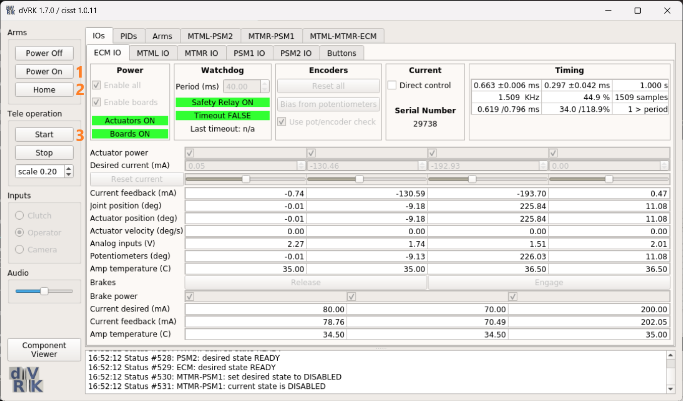
With the console open you can start the daVinci robot by pressing, in order:
-
Power On[1] --> Then wait for the all the red labels on the console to turn green -
Home[2] --> The MTMs will move to their home position and orientation (pointing away from you) -
Start[3] --> The MTMs will move to their starting pose (pointing down and inward)
At this point, the robot is ready.
You may find the MTMs rigid and you may see a red error message in the control panel stating:
Pinching action required
Just pinch both the left and right grippers of the manipulators and the MTMs will be free to move.
Unity cannot natively read ROS messages. In order to communicate with ROS, we need to use a bridge that translates ROS messages into a format that Unity can understand, JSON in this case. The ROSBridge package makes this conversion possible.
Open a new terminal on the dVRK computer and launch the ROSBridge server with
roslaunch rosbridge_server rosbridge_websocket.launch
or its alias
roslaunchserver
If you see this green confirmation message, the server is running correctly and Unity will read the ROS messages seamlessly:
ROSBridge server started correctly
>> IP = 192.168.1.2
>> Port = 9090
To lauch the ROSPackage built for STEVE, open a new terminal on the GRU computer and launch the ROSPackage with
roslaunch steve steve.launch
After a couple of seconds, you should see the confirmation prompt:
> Gravity compensation is ACTIVE on Right-MTM
> Gravity compensation is ACTIVE on Left-MTM
> Teleoperation scale initialized to 0.5
> Left-MTM RF set to BASE
> Right-MTM RF set to BASE
> Wrench Safety buffer initialized
> Joint Velocity Safety Virtual Relay Initialized
Open the Unity project and launch one of the scenes. You can also launch one of the scenes directly from the Assets folder by double-clicking the .unityscene file. If you open Playground.unityscene you will see the following window:
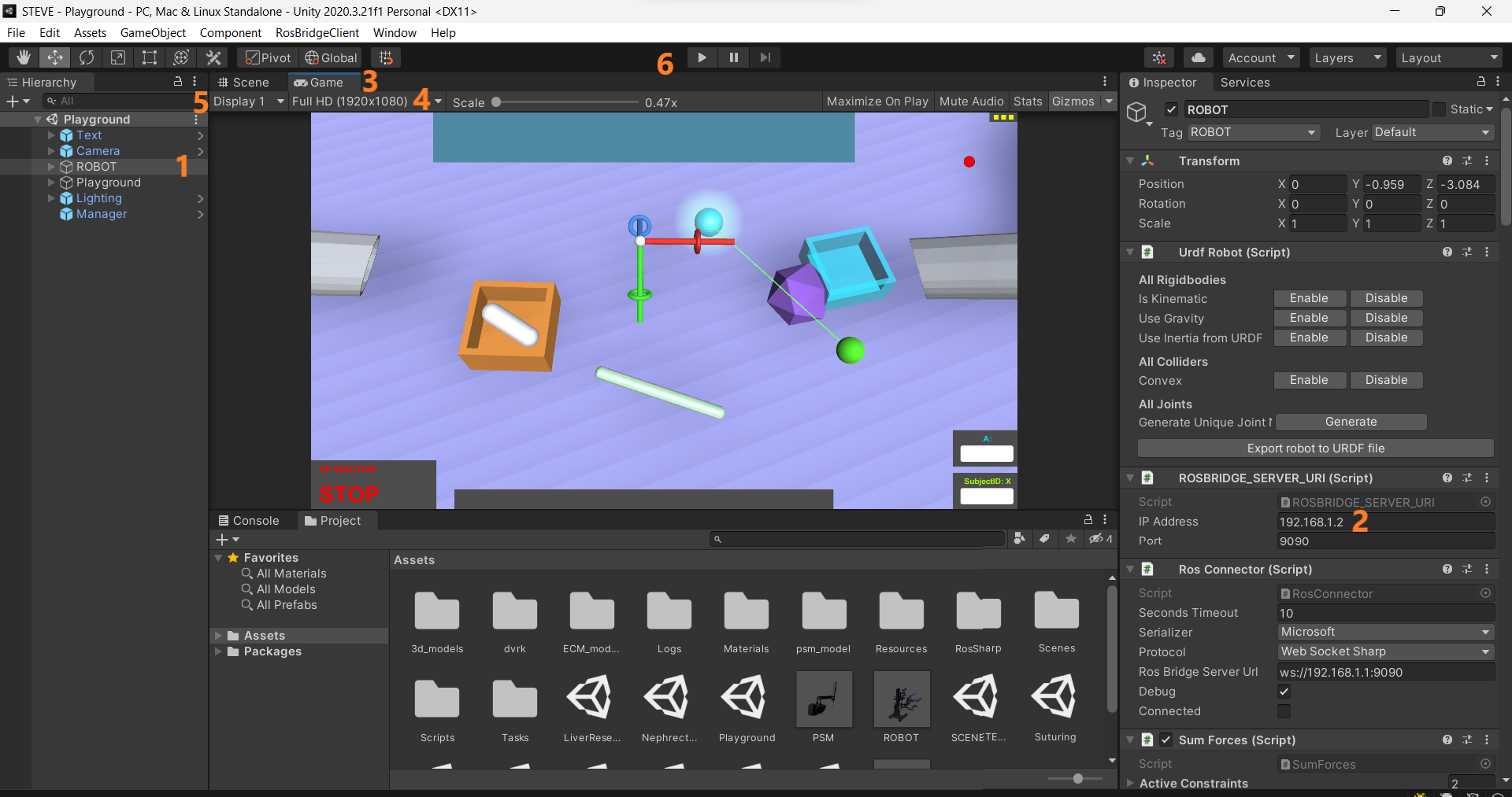
With the Unity window open, you must specify the IP address of the computer where the ROSBridge server is running, dVRK, so select the ROBOT [1] object from the Hierarchy on the left, find the ROSBRIDGE_SERVER_URI [2] component in the Property Inspector (usually on the right side of the Unity window) and set 192.168.1.2 in the "IP" field. (This field should be set by default and this passage may not be required)
If they are not visible already, open two additional Game tabs. You can do this (two times to open two Game windows) by:
- Right-clicking on the
Gametab on the top of the Unity window [3] Add TabGame
Close to the tab top-left corner, set the resolution to Full HD (1920x1080) [4]. Now, assign each of the two Game tabs to receive the feed from one of the two virtual cameras. On the top-left corner [5]:
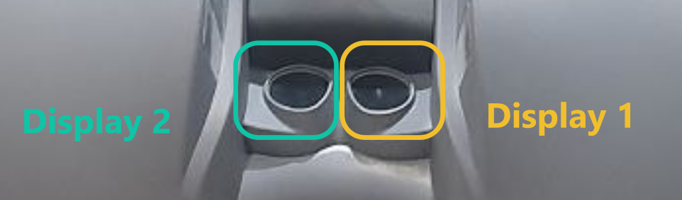
- Assign
Display 1to theGametab that will go on the RIGHT HRSV ocular - Assign
Display 2to theGametab that will go on the LEFT HRSV ocular
Now, drag the Game tabs out of the edges of your main monitor and place them on the two HRSV oculars, minding the .
If the Displays are assigned correctly, the resolution is Full HD and the Game windows are both maximizes, you should be able to see the Virtual Unity scene in 3D.
At this point, you can start using the simulator. Press the Unity Play button [6] to start the simulation. If you are correctly connected to the ROSBridge server, you should see the following message in the Unity console:
ROBOT: CONNECTED to RosBridge @ ws://192.168.1.2:9090
TROUBLESHOOTING: If the connection fails, you will see the following warning:
ROBOT: FAILED to connect to RosBridge @ ws://192.168.1.2:9090
If that is the case, check that you followed the previous steps. Usually::
- The ROSBridge server is not running (check the terminal where you launched the server and make sure that the confirmation message is displayed)
- The IP address and/or the port of the ROSBridge server is not correct (check that the IP address in the Unity Property Inspector is correct, the port is 9090 by default)
- The ROSMaster is not running on
GRU - Your computer is not communicating for some reasons. In a terminal, try the command
ping 192.168.1.2and check that the terminal outputs64 bytes from 192.168.1.2: icmp_seq=1 ttl=XXX time=XXX msat least once - The Ethernet cable is not inserted properly
You should be now ready to move the MTMs, and the PSMs will move in the virtual environment accordingly.
Here is a list of the commands:
| Command | Keyboard | Surgeon Console |
|---|---|---|
| Select surgical scene | Numbers 0-8 |
+ pedal |
| Reset current scene | Numbers 0-8 |
- pedal |
| Toggle Haptic Assitance | V |
Bicoag pedal |
| Start to log data | L |
Coag pedal |
| Emergency remove Haptic Assistance | O |
|
| Hide/Show debug panel | D |
The surgical scenes have a code number, to be selected from the keyboard:
| Scene | Numerical Code |
|---|---|
| Playground | 0 |
| Path / Training1 | 1 |
| Rings / Training2 | 2 |
| Pillars / Training3 | 3 |
| Exchange / Training4 | 4 |
| Thymectomy | 5 |
| Nephrectomy | 6 |
| Liver Resection | 7 |
| Suturing | 8 |