System Reference Manual
v
PocketBeagle
System Reference Manual (SRM)
Revision A.x (on-line wiki edition)
December 6, 2017
Maintaining author: Jason Kridner jkridner@beagleboard.org
Contributing Editor: Cathy Wicks cathy@beagleboard.org
THIS DOCUMENT
Terms These design materials are *NOT SUPPORTED* and *DO NOT* constitute a reference design. Only “community” support is allowed via resources at BeagleBoard.org/discuss.
THERE IS NO WARRANTY FOR THE DESIGN MATERIALS, TO THE EXTENT PERMITTED BY APPLICABLE LAW. EXCEPT WHEN OTHERWISE STATED IN WRITING THE COPYRIGHT HOLDERS AND/OR OTHER PARTIES PROVIDE THE DESIGN MATERIALS “AS IS” WITHOUT WARRANTY OF ANY KIND, EITHER EXPRESSED OR IMPLIED, INCLUDING, BUT NOT LIMITED TO, THE IMPLIED WARRANTIES OF MERCHANTABILITY AND FITNESS FOR A PARTICULAR PURPOSE. THE ENTIRE RISK AS TO THE QUALITY AND PERFORMANCE OF THE DESIGN MATERIALS IS WITH YOU. SHOULD THE DESIGN MATERIALS PROVE DEFECTIVE, YOU ASSUME THE COST OF ALL NECESSARY SERVICING, REPAIR OR CORRECTION.
In other words, you may use the design materials as you choose and there is no license with regards to usage in the manufacturing process. We mean it, these design materials may be totally unsuitable for any purposes. Don't blame us!
As a general rule, we don't encourage use of this or other off-the-shelf single board computers in commercial products without engaging with a manufacturer to create a supplier agreement and make sure that you can get material as your business demands. Further, we do update the design on occasions where we find it necessary and won't guarantee a supply of older revisions, though we do seek periodic manufacturing of all of our boards for a period of roughly 10 years and will make design changes to replace obsolete parts and that may impact your usage. If you do opt to use it in a product, you take full responsibility for that product.
Do not use the BeagleBoard.org logo or trademarks (such as BeagleBoard, BeagleBone and PocketBeagle) on your products without a logo license from the BeagleBoard.org Foundation, but feel free to reference BeagleBoard.org.
See the LICENSE file regarding the copyright of these materials.
This document is the System Reference Manual for PocketBeagle and covers its use and design. PocketBeagle is an ultra-tiny-yet-complete Linux-enabled, community-supported, open-source USB-key-fob-computer. PocketBeagle features an incredible low cost, slick design and simple usage, making it the ideal development board for beginners and professionals alike. Simply develop directly in a web browser providing you with a playground for programming and electronics. Exploring is made easy with several available libraries and tutorials with many more coming.
PocketBeagle will boot directly from a microSD card. Load a Linux distribution onto your card, plug your board into your computer and get started. PocketBeagle runs GNU.Linux, so you can leverage many different high-level programming languages and a large body of drivers that prevent you from needing to write a lot of your own software.
This design will keep improving as the product matures based on feedback and experience. Software updates will be frequent and will be independent of the hardware revisions and as such not result in a change in the revision number of the board. A great place to find out the latest news and projects for PocketBeagle is on the home page beagleboard.org/pocket

Make sure you check the support Wiki frequently for the most up to date information. github.com/beagleboard/pocketbeagle/wiki
This section describes the change history of this document and board. Document changes are not always a result of a board change. A board change will always result in a document change.
| Rev | Changes | Date | By |
|---|---|---|---|
| A.x | Production Document | December 7, 2017 | JK |
| Rev | Changes | Date | By |
|---|---|---|---|
| A1 | Preliminary | February 14, 2017 | JK |
| A2 | Production. Fixed mikroBUS Click reset pins (made GPIO). | September 22, 2017 | JK |
Upon the creation of the first, 27mm-by-27mm, Octavo Systems OSD3358 SIP, Jason did a hack two-layer board in EAGLE called “PocketBone” to drop the Beagle name as this was a totally unofficial effort not geared at being a BeagleBoard.org Foundation project. The board never worked because the 32kHz and 24MHz crystals were backwards and Michael Welling decided to pick it up and redo the design in KiCad as a four-layer board. Jason paid for some prototypes and this resulted in the first successful “PocketBone”, a fully-open-source 1-GHz Linux computer in a fitting into a mini-mint tin.
The Rev A1 of PocketBeagle was a prototype not released to production. A few lines were wrong to be able to control mikroBUS Click add-on board reset lines and they were adjusted.
The Rev A2 of PocketBeagle was released to production and at World MakerFaire 2017.
Known issues in rev A2:
| Issue | Link |
|---|---|
| GPIO44 is incorrectly labelled as GPIO48 | github.com/beagleboard/pocketbeagle/issues/4 |
This section provides instructions on how to hook up your board. The most common scenario is tethering PocketBeagle to your PC for local development.
In the package you will find two items as shown in Figures 2 and 3.
- PocketBeagle
- Getting Started instruction card with link to the support URL.


This section will describe how to connect to the board. Information can also be found on the Quick Start Guide that came in the box. Detailed information is also available at beagleboard.org/getting-started
The board can be configured in several different ways, but we will discuss the most common scenario. Future revisions of this document may include additional configurations.
In this configuration, you will need the following additional items:
- microUSB to USB Type A Cable
- microSD card (>=4GB and <128GB)

In some instances, such as when additional add-on boards, or PocketCapes are connected, the PC may not be able to supply sufficient power for the full system. In that case, review the power requirements for the add-on board/cape; additional power may need to be supplied via the 5v input, but rarely is this the case.
The following steps will guide you to quickly download a PocketBeagle software image onto your microSD card and get started writing code.
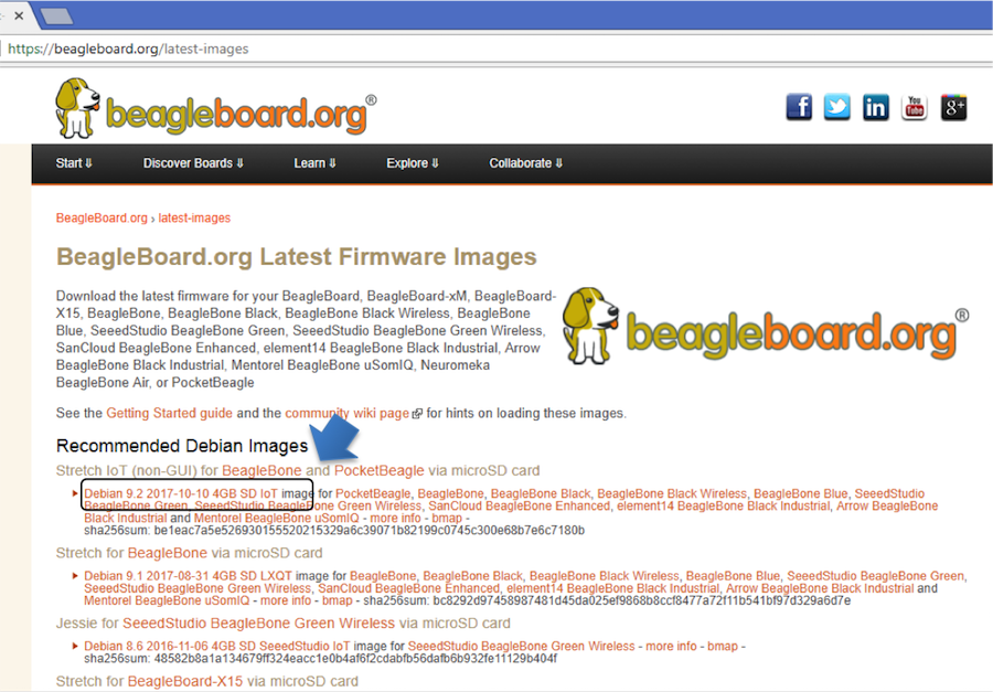
1. Navigate to the Getting Started Page beagleboard.org/getting-started Follow along with the instructions and click on the link noted in Figure 5 below beagleboard.org/latest-images. You can also get to this page directly by going to bbb.io/latest

2. Download the latest image onto your computer by following the link to the latest image and click on the Debian image for Stretch IoT (non-GUI) for BeagleBone and PocketBeagle via microSD card. See Figure 6 below. This will download a .img.xz file into the downloads folder of your computer.
3. Transfer the image to a microSD card.
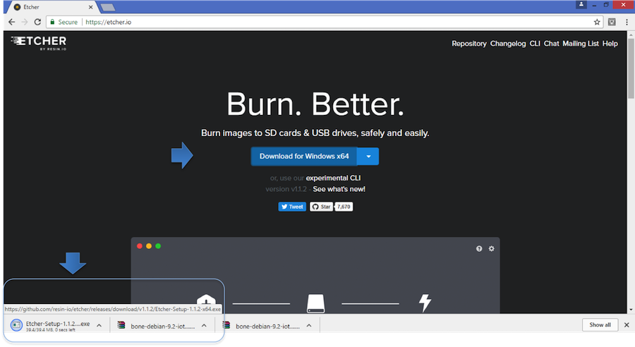
Download and install an SD card programming utility if you do not already have one. We like https://etcher.io/ for new users and so we show that one in the steps below. Go to your downloads folder and doubleclick on the .exe file and follow the on-screen prompts. See figure 7.
Insert a new microSD card into a card reader/writer and attach it via the USB connection to your computer. Follow the instructions on the screen for selecting the .img file and burning the image from your computer to the microSD card. Eject the SD card reader when prompted and remove the card. See Figures 8 and 9.


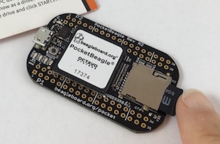
4. Insert the microSD card into the board - you'll hear a satisfying click when it seats properly into the slot. It is important that your microSD card is fully inserted prior to powering the system.
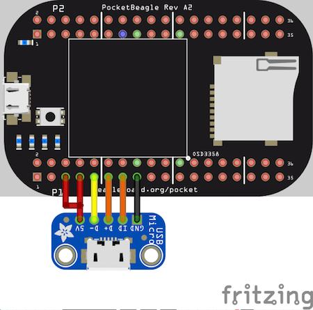
5. Connect the micro USB connector on your cable to the board as shown in Figure 11. The microUSB connector is fairly robust, but we suggest that you not use the cable as a leash for your PocketBeagle. Take proper care not to put too much stress on the connector or cable.

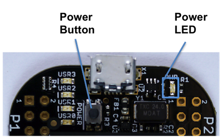
6. Connect the large connector of the USB cable to your Linux, Mac or Windows PC USB port as shown in Figure 12. The board will power on and the power LED will be on as shown in Figure 13 below.


7. As soon as you apply power, the board will begin the booting process and the userLEDs Figure 14 will come on in sequence as shown below. It will take a few seconds for the status LEDs to come on, like teaching PocketBeagle to 'stay'. The LEDs will be flashing as it begins to boot the Linux kernel. While the four user LEDS can be over written and used as desired, they do have specific meanings in the image that you've initially placed on your microSD card once the Linux kernel has booted.
- USER0 is the heartbeat indicator from the Linux kernel.
- USER1 turns on when the microSD card is being accessed
- USER2 is an activity indicator. It turns on when the kernel is not in the idle loop.
- USER3 idle

The board will appear as a USB Storage drive on your PC after the kernel has booted, which will take approximately 10 seconds. The kernel on the board needs to boot before the port gets enumerated. Once the board appears as a storage drive, do the following:
1. Open the USB Drive folder to view the files on your PocketBeagle.
2. Launch Interactive Quick Start Guide.
Right Click on the file named START.HTM and open it in Chrome or Firefox. This will use your browser to open a file running on PocketBeagle via the microSD card. You will see file:///Volumes/BEAGLEBONE/START.htm in the url bar of the browser. See Figure 15 below. This action displays an interactive Quick Start Guide from PocketBeagle.

3. Enable a Network Connection.
Click on 'Step 2' of the Interactive Quick Start Guide page to follow instructions to "Enable a Network Connection" (pointing to the DHCP server that is running on PocketBeagle). Copy the appropriate IP Address from the chart (according to your PC operating system type) and paste into your browser then add a :3000 to the end of it. See example in Figure 16 below. This will launch from PocketBeagle one of it's favorite Web Based Development Environments, Cloud9 IDE, (Figure 17) so that you can teach your beagle new tricks!


4. Get Started Coding with Cloud9 IDE - blinking USR3 LED in JavaScript using the BoneScript library example
- Create a new text file
- Copy and paste the below code into the editor
var b = require('bonescript'); var state = b.LOW; b.pinMode("USR3", b.OUTPUT); setInterval(toggle, 250); // toggle 4 times a second, every 250ms function toggle() { if(state == b.LOW) state = b.HIGH; else state = b.LOW; b.digitalWrite("USR3", state); } - Save the new text file as blinkusr3.js within the default directory
- Execute
node blinkusr3.js
within the default (/var/lib/cloud9) directory - Type CTRL+C to stop the program running


1. Standard Power Down
Press the power button momentarily with a tap. The system will power down automatically. This will shut down your software with grace. Software routines will run to completion.
The Standard Power Down can also be invoked from the Linux command shell via "sudo shutdown -h now".
2. Hard Power Down Press the power button for 10 seconds. This will force an immediate shut down of the software. For example you may lose any items you have written to the memory. Holding the button longer than 10 seconds will perform a power reset and the system will power back on.
3. Remove the USB cable Remember to hold your board firmly at the USB connection while you remove the cable to prevent damage to the USB connector.
4. Powering up again. If you'd like to power up again without removing the USB cable follow these instructions:
- If you used Step 1 above to power down, to power back up, hold the power button for 10 seconds, release then tap it once and the system will boot normally.
- If you used Step 2 above to power down, to power back up, simply tap the power button and the system will boot normally.
The board can be configured in several different ways. Future revisions of this document may include additional configurations.
As other examples become documented, we'll update them on the Wiki for PocketBeagle github.com/beagleboard/pocketbeagle/wiki See also the on-line discussion.
PocketBeagle is built around Octavo Systems' OSD335x-SM System-In-Package that integrates a high-performance Texas Instruments AM3358 processor, 512MB of DDR3, power management, nonvolatile serial memory and over 100 passive components into a single package. This integration saves board space by eliminating several packages that would otherwise need to be placed on the board, but more notably simplifies our board design so we can focus on the user experience.
The compact PocketBeagle design also offers access through the expansion headers to many of the interfaces and allows for the use of add-on boards called PocketCapes and Click Boards from MikroElektronika, to add many different combinations of features. A user may also develop their own board or add their own circuitry.
This section covers the specifications and features of the board in a chart and provides a high level description of the major components and interfaces that make up the board.
| Feature | ' |
|---|---|
| System-In-Package | Octavo Systems OSD335x-SM in 256 Ball BGA (21mm x 21mm) |
| SiP Incorporates : | |
| Processor | Texas Instruments 1GHz Sitara™ AM3358 ARM® Cortex®-A8 with NEON floating-point accelerator |
| Graphics Engine | Imagination Technologies PowerVR SGX530 Graphics Accelerator |
| Real-Time Units | 2x programmable real-time unit (PRU) 32-bit 200MHz microcontrollers with single-cycle I/O latency |
| Coprocessor | ARM® Cortex®-M3 for power management functions |
| SDRAM Memory | 512MB DDR3 800MHz RAM |
| Non-Volatile Memory | 4KB I2C EEPROM for board configuration information |
| Power Management | TPS65217C PMIC along with TL5209 LDO to provide power to the system with integrated 1-cell LiPo battery support (for more info about battery usage see OCTAVO APP NOTE) |
| Connectivity : | |
| SD/MMC | Bootable microSD card slot |
| USB | High speed USB 2.0 OTG (host/client) micro-B connector |
| Debug Support | JTAG test points and gdb/other monitor-mode debug possible |
| Power Source | microUSB connector, also expansion header options (battery, VIN or USB-VIN) |
| User I/O | Power Button with press detection interrupt via TPS65217C PMIC |
| Expansion Header : | |
| USB | High speed USB 2.0 OTG (host/client) control signals |
| Analog Inputs | 8 analog inputs with 6 @ 1.8V and 2 @ 3.3V along with 1.8V references |
| Digital I/O | 44 digital GPIOs accessible with 18 enabled by default including 2 shared with the 3.3V analog input pins |
| UART | 3 UARTs accessible with 2 enabled by default |
| I2C | 2 I2C busses enabled by default |
| SPI | 2 SPI busses with single chip selects enabled by default |
| PWM | 4 Pulse Width Modulation outputs accessible with 2 enabled by default |
| QEP | 2 Quadrature encoder inputs accessible |
| CAN | 2 CAN bus controllers accessible |
The Octavo Systems OSD3358-512M-BSM System-In-Package (SiP) is part of a family of products that are building blocks designed to allow easy and cost-effective implementation of systems based in Texas Instruments powerful Sitara AM335x line of processors. The OSD335x-SM integrates the AM335x along with the TI TPS65217C PMIC, the TI TL5209 LDO, up to 1 GB of DDR3 Memory, a 4 KB EEPROM for non-volatile configuration storage and resistors, capacitors and inductors into a single 21mm x 21mm design-in-ready package.
With this level of integration, the OSD335x-SM family of SiPs allows designers to focus on the key aspects of their system without spending time on the complicated high-speed design of the processor/DDR3 interface or the PMIC power distribution. It reduces size and complexity of design.
Full Datasheet and more information is available at octavosystems.com/octavo_products/osd335x-sm/
This section describes the key components on the board, their location and function.
Figure 21 below shows the locations of the devices, connectors, LEDs, and switches on the PCB layout of the board.

Key Components
- The Octavo Systems OSD3358-512M-BSM System-In-Package is the processor system for the board
- P1 and P2 Headers come unpopulated so a user may choose their orientation
- User LEDs provides 4 programmable blue LEDs
- Power BUTTON can be used to power up or power down the board (see section 3.3.3 for details)
- USB 2.0 OTG is a microUSB connection to a PC that can also power the board
- Power LED provides communication regarding the power to the board
- microSD slot is where a microSD card can be installed.
This section provides the high level specification of PocketBeagle.
Figure 22 below is the high level block diagram of PocketBeagle.

The OSD335x-SM Block Diagram is detailed in Figure 23 below. More information, including design resources are available on the 'Octavo Systems Website'
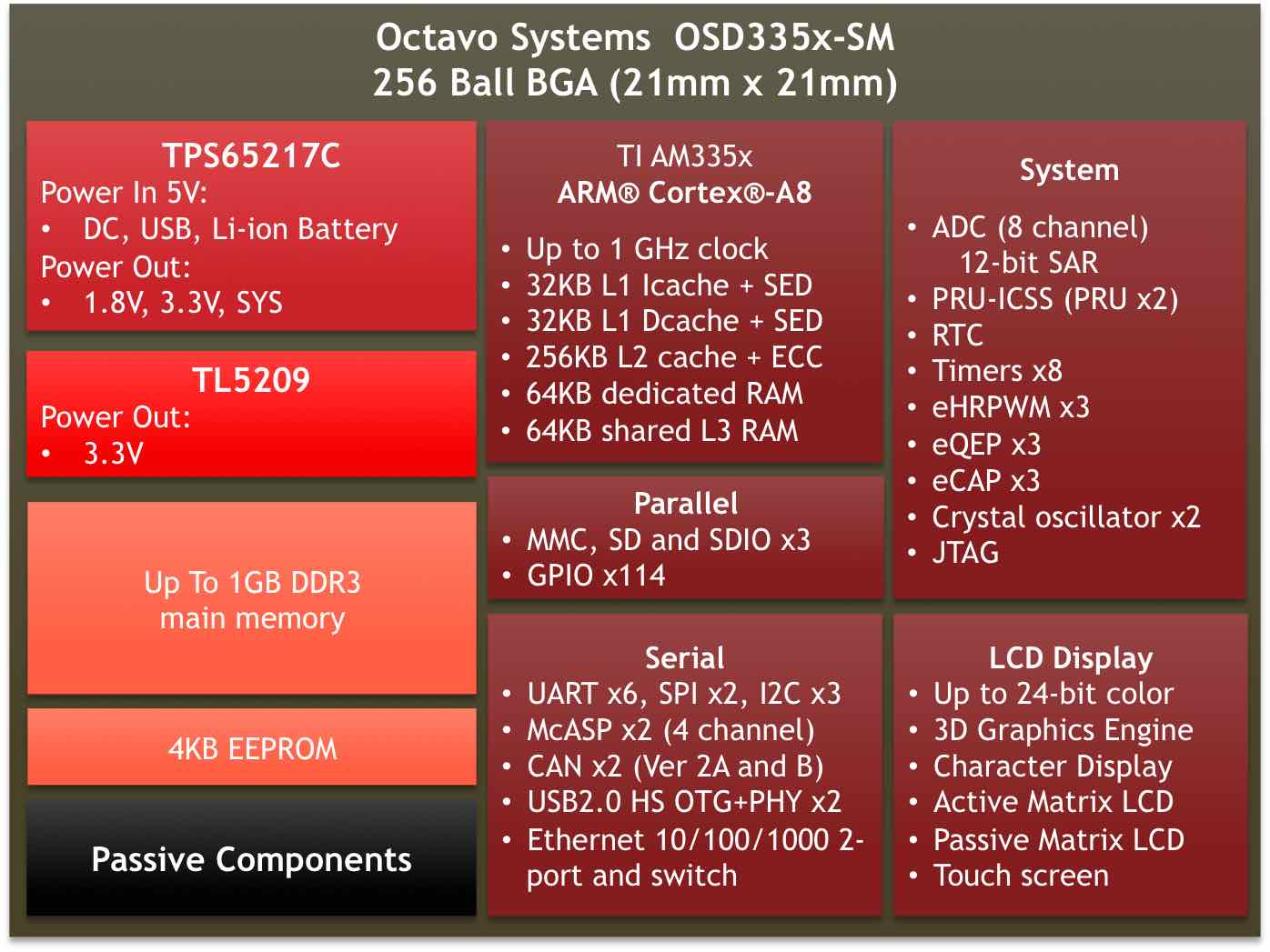
Note: PocketBeagle utilizes the 512MB DDR3 memory size version of the OSD335x-SM A few of the features of the OSD335x-SM SiP may not be available on PocketBeagle headers. Please check Section 7 for the P1 and P2 header pin tables.
PocketBeagle gives access to a large number of peripheral functions and GPIO via 2 dual rail expansion headers. With 36 pins each, the headers have been left unpopulated to enable users to choose the header connector orientation or add-on board / cape connector style. Pins are clearly marked on the bottom of the board with additional pin configurations available through software settings. Detailed information is available in Section 7.

The board is equipped with a single microSD connector to act as the primary boot source for the board. Just about any microSD card you have will work, we commonly find 4G to be suitable.
When plugging in the SD card, the writing on the card should be up. Align the card with the connector and push to insert. Then release. There should be a click and the card will start to eject slightly, but it then should latch into the connector. To eject the card, push the SD card in and then remove your finger. The SD card will be ejected from the connector. Do not pull the SD card out or you could damage the connector.

The board has a microUSB connector that is USB 2.0 HS compatible that connects the USB0 port to the SiP. Generally this port is used as a client USB port connected to a power source, such as your PC, to power the board. If you would like to use this port in host mode you will need to supply power for peripherals via Header P1 pin 7 (USB1.VIN) or through a powered USB Hub. Additionally, in the USB host configuration, you will need to power the board through Header P1 pin 1 (VIN) or Header P1 pin 7 (USB1.VIN) or Header P2 pin 14 (BAT.VIN)

There are three boot modes:
- SD Boot: MicroSD connector acts as the primary boot source for the board. This is described in Section 3.
- USB Boot: This mode supports booting over the USB port. More information can be found in the project called "BeagleBoot" This project ported the BeagleBone bootloader server BBBlfs(currently written in c) to JavaScript(node.js) and make a cross platform GUI (using electron framework) flashing tool utilizing the etcher.io project. This will allow a single code base for a cross platform tool. For more information on BeagleBoot, see the BeagleBoot Project Page.
- Serial Boot: This mode will use the serial port to allow downloading of the software. A separate USB to TTL level serial UART converter cable is required or you can connect one of the Mikroelektronika FTDI Click Boards to use this method. The UART pins on PocketBeagle's expansion headers support the interface. For more information regarding the pins on the expansion headers and various modes, see Section 7.
| Header.Pin | Silkscreen | Proc Ball | SiP Ball | Pin Name (Mode 0) |
| P1.22 | GND | GND | ||
| P1.30 | U0_TX | E16 | B12 | uart0_txd |
| P1.32 | U0_RX | E15 | A12 | uart0_rxd |
If the Serial Boot is not in use, the UART0 pins can be used for Serial Debug. See Section 5.6 for more information.
Software to support USB and serial boot modes is not provided by beagleboard.org. Please contact TI for support of this feature.
The board can be powered from three different sources:
- A USB port on a PC.
- A power supply with a USB connector.
- Expansion Header pins.
The tables below show the power related pins available on PocketBeagle's Expansion Headers.
| Header.Pin | Silkscreen | Proc Ball | SiP Ball | Pin Name (Mode 0) |
| P1.01 | VIN | P10, R10, T10 | VIN | |
| P1.07 | USB1_VI | P9, R9, T9 | VIN-USB | |
| P2.14 | BAT_+ | P8, R8, T8 | VIN-BAT |
| Header.Pin | Silkscreen | Proc Ball | SiP Ball | Pin Name (Mode 0) |
| P1.14 | +3.3V | F6, F7, G6, G7 | VOUT-3.3V | |
| P1.24 | VOUT | K6, K7, L6, L7 | VOUT-5V | |
| P2.13 | VOUT | K6, K7, L6, L7 | VOUT-5V | |
| P2.23 | +3.3V | F6, F7, G6, G7 | VOUT-3.3V |
| Header.Pin | Silkscreen | Proc Ball | SiP Ball | Pin Name (Mode 0) |
| P1.15 | USB1_GND | GND | ||
| P1.16 | GND | GND | ||
| P1.22 | GND | GND | ||
| P2.15 | GND | GND | ||
| P2.21 | GND | GND |
Note: A comprehensive tutorial for Power Inputs and Outputs for the OSD335x System in Package is available in the 'Tutorial Series' on the Octavo Systems website.
Pads for an optional connection to a JTAG emulator has been provided on the back of PocketBeagle. More information about JTAG emulation can be found on the TI website - 'Entry-level debug through full-capability development'

Serial debug is provided via UART0 on the processor. See Section 5.3.4 for the Header Pin table. Signals supported are TX and RX. None of the handshake signals (CTS/RTS) are supported. A separate USB to TTL level serial UART converter cable is required or you can connect one of the Mikroelektronika FTDI Click Boardsto use this method.

If serial boot is not used, the UART0 can be used to view boot messages during startup and can provide access to a console using a terminal access program like Putty. To view the boot messages or use the console the UART should be set to a baud rate of 115200 and use 8 bits for data, no parity bit and 1 stop bit (8N1).
The following sections contain schematic references for PocketBeagle. Full schematics in both PDF and Eagle are available on the 'PocketBeagle Wiki'
Schematics for the OSD3358-SM SiP are divided into several diagrams.


The Micro Secure Digital (microSD) connector design is highlighted in Figure 35.

The USB connector design is highlighted in Figure 36.
Note that there is an ID pin for dual-role (host/client) functionality. The hardware fully supports it, but care should be taken to ensure the kernel in use is either statically or dynamically configured to recognize and utilize the proper mode.

The power button design is highlighted in Figure 37.

There are four user programmable LEDs on PocketBeagle. The design is highlighted in Figure 38. Table 6 Provides the LED control signals and pins. A logic level of "1" will cause the LEDs to turn on.

| LED | Signal Name | Proc Ball | SiP Ball |
| USR0 | GPIO1_21 | V15 | P13 |
| USR1 | GPIO1_22 | U15 | T14 |
| USR2 | GPIO1_23 | T15 | R14 |
| USR3 | GPIO1_24 | V16 | P14 |
There are 7 pads on the bottom of PocketBeagle to connect JTAG for debugging. The design is highlighted in Figure 39. More information regarding JTAG debugging can be found at 'www.ti.com/jtag'

The Programmable Real-Time Unit Subsystem and Industrial Communication SubSystem (PRU-ICSS) module is located inside the AM3358 processor, which is inside the Octavo Systems SiP. Commonly referred to as just the "PRU", this little subsystem will unleash a lot of performance for you to use in your application. Consisting of dual 32-bit RISC cores (Programmable Real-Time Units, or PRUs), data and instruction memories, internal peripheral modules, and an interrupt controller (INTC). The programmable nature of the PRU-ICSS, along with their access to pins, events and all SoC resources, provides flexibility in implementing fast real-time responses, specialized data handling operations, custom peripheral interfaces, and in offloading tasks from the other processor cores of the system-on-chip (SoC). Access to these pins is provided by PocketBeagle's expansion headers and is multiplexed with other functions on the board. Access is not provided to all of the available pins.
Some getting started information can be found on https://beagleboard.org/pru.
Additional documentation is located on the Texas Instruments website at processors.wiki.ti.com/index.php/PRU-ICSS and also located at http://github.com/beagleboard/am335x_pru_package.
Example projects using the PRU-ICSS can be found at processors.wiki.ti.com/index.php/PRU_Projects.
The features of the PRU-ICSS include:
Two independent programmable real-time (PRU) cores:
- 32-Bit Load/Store RISC architecture
- 8K Byte instruction RAM (2K instructions) per core
- 8K Bytes data RAM per core
- 12K Bytes shared RAM
- Operating frequency of 200 MHz
- PRU operation is little endian similar to ARM processor
- All memories within PRU-ICSS support parity
- Includes Interrupt Controller for system event handling
- Fast I/O interface
Figure 40 is a high level block diagram of the PRU-ICSS.

Both PRU 0 and PRU1 are accessible from the expansion headers. Listed below are the ports that can be accessed on each PRU.
Table 6. below shows which PRU-ICSS signals can be accessed on PocketBeagle and on which connector and pins on which they are accessible. Some signals are accessible on the same pins.
Use scroll bar at bottom of chart to see additional features in columns to the right. When printing this document, you will need to print this chart separately.
| Header.Pin | Silkscreen | Processor Ball | SiP Ball | Mode3 | Mode4 | Mode5 | Mode6 | Note |
| P1.02 | A6/87 | R5 | F2 | pr1_pru1_pru_r30_9 (Output) | pr1_pru1_pru_r31_9 (Input) | |||
| P1.04 | 89 | R6 | E1 | pr1_pru1_pru_r30_11 (Output) | pr1_pru1_pru_r31_11 (Input) | |||
| P1.06 | SPI0_CS | A16 | A14 | pr1_uart0_txd (Output) | UART Transmit Data | |||
| P1.08 | SPI0_CLK | A17 | A13 | pr1_uart0_cts_n (Input) | UART Clear to Send | |||
| P1.10 | SPI0_MISO | B17 | B13 | pr1_uart0_rts_n (Output) | UART Request to Send | |||
| P1.12 | SPI0_MOSI | B16 | B14 | pr1_uart0_rxd (Input) | UART Receive Data | |||
| P1.20 | 20 | D14 | B4 | pr1_pru0_pru_r31_16 (Input) | ||||
| P1.26 | I2C2_SDA | D18 | B10 | pr1_uart0_cts_n (Input) | UART Clear to Send | |||
| P1.28 | I2C2_SCL | D17 | A10 | pr1_uart0_rts_n (Output) | UART Request to Send | |||
| P1.29 | PRU0_7 | A14 | C4 | pr1_pru0_pru_r30_7 (Output) | pr1_pru0_pru_r31_7 (Input) | |||
| P1.30 | U0_TX | E16 | B12 | pr1_pru1_pru_r30_15 (Output) | pr1_pru1_pru_r31_15 (Input) | |||
| P1.31 | PRU0_4 | B12 | A3 | pr1_pru0_pru_r30_4 (Output) | pr1_pru0_pru_r31_4 (Input) | |||
| P1.32 | U0_RX | E15 | A12 | pr1_pru1_pru_r30_14 (Output) | pr1_pru1_pru_r31_14 (Input) | |||
| P1.33 | PRU0_1 | B13 | A2 | pr1_pru0_pru_r30_1 (Output) | pr1_pru0_pru_r31_1 (Input) | |||
| P1.35 | P1.10 | V5 | F1 | pr1_pru1_pru_r30_10 (Output) | pr1_pru1_pru_r31_10 (Input) | |||
| P1.36 | PWM0A | A13 | A1 | pr1_pru0_pru_r30_0 (Output) | pr1_pru0_pru_r31_0 (Input) | |||
| P2.09 | I2C1_SCL | D15 | B11 | pr1_uart0_txd (Output) | pr1_pru0_pru_r31_16 (Input) | UART Transmit Data | ||
| P2.11 | I2C1_SDA | D16 | A11 | pr1_uart0_rxd (Input) | pr1_pru1_pru_r31_16 (Input) | UART Receive Data | ||
| P2.17 | 65 | V12 | T7 | pr1_mdio_mdclk | MDIO Clk | |||
| P2.18 | 47 | U13 | P7 | pr1_ecap0_ecap_capin_apwm_o | pr1_pru0_pru_r31_15 (Input) | Enhanced capture input or Auxiliary PWM out | ||
| P2.20 | 64 | T13 | R7 | pr1_mdio_data | MDIO Data | |||
| P2.22 | 46 | V13 | T6 | pr1_pru0_pru_r31_14 (Input) | ||||
| P2.24 | 48 | T12 | P6 | pr1_pru0_pru_r30_14 (Output) | ||||
| P2.28 | PRU0_6 | D13 | C3 | pr1_pru0_pru_r30_6 Output) | pr1_pru0_pru_r31_6 (Input) | |||
| P2.29 | SPI1_CLK | C18 | C5 | pr1_ecap0_ecap_capin_apwm_o | Enhanced capture input or Auxiliary PWM out | |||
| P2.30 | PRU0_3 | C12 | B1 | pr1_pru0_pru_r30_3 (Output) | pr1_pru0_pru_r31_3 (Input) | |||
| P2.31 | SPI1_CS | A15 | A4 | pr1_pru1_pru_r31_16 (Input) | ||||
| P2.32 | PRU0_2 | D12 | B2 | pr1_pru0_pru_r30_2 (Output) | pr1_pru0_pru_r31_2 (Input) | |||
| P2.33 | 45 | R12 | R6 | pr1_pru0_pru_r30_15 (Output) | ||||
| P2.34 | PRU0_5 | C13 | B3 | pr1_pru0_pru_r30_5 (Output) | pr1_pru0_pru_r31_5 (Input) | |||
| P2.35 | A5/86 | U5 | F3 | pr1_pru1_pru_r30_8 (Output) | pr1_pru1_pru_r31_8 (Input) |
This section describes each of the connectors on the board.
The expansion interface on the board is comprised of two 36 pin connectors. The two Expansion Header Connectors on PocketBeagle are labeled P1 and P2. The connections are a standard 100 mil distance so that they can be compatible with many standard expansion items. The silkscreen for the headers on the bottom of the board provides the easiest way to identify them. See Figure 41.

All signals on the expansion headers are 3.3V unless otherwise indicated.
NOTE: Do not connect 5V logic level signals to these pins or the board will be damaged.
NOTE: DO NOT APPLY VOLTAGE TO ANY I/O PIN WHEN POWER IS NOT SUPPLIED TO THE BOARD. IT WILL DAMAGE THE PROCESSOR AND VOID THE WARRANTY.
NO PINS ARE TO BE DRIVEN UNTIL AFTER THE NRESET LINE GOES HIGH.
Figure 42 shows a color coded chart with an overview of the most popular functions of PocketBeagle's Expansion Header pins. The Header Pin tables in Sections 7.1.1 and 7.1.2 show the full pin assignments for each header.

Figure 43 shows the schematic diagram for the P1 Header.

Use scroll bar at bottom of chart to see additional features in columns to the right. When printing this document you will need to print this chart separately.
| Header.Pin | Silkscreen | PocketBeagle wiring | Proc Ball | SiP Ball | Mode0 (Name) | Mode1 | Mode2 | Mode3 | Mode4 | Mode5 | Mode6 | Mode7 |
| P1.01 | VIN | P1.01 (VIN) | P10 & R10 & T10 | VIN | ||||||||
| P1.02 | A6/87 | P1.02 (AIN6/GPIO87) | A8 | C9 | ain6 | |||||||
| P1.02 | A6/87 | P1.02 (AIN6/GPIO87) | R5 | F2 | lcd_hsync | gpmc_a9 | gpmc_a2 | pr1_edio_data_in3 | pr1_edio_data_out3 | pr1_pru1_pru_r30_9 | pr1_pru1_pru_r31_9 | gpio2_23 |
| P1.03 | USB1_EN | P1.03 (USB1-DRVVBUS) | F15 | M14 | USB1_DRVVBUS | - | - | - | - | - | - | gpio3_13 |
| P1.04 | 89 | P1.04 (PRU1.11) | R6 | E1 | lcd_ac_bias_en | gpmc_a11 | pr1_mii1_crs | pr1_edio_data_in5 | pr1_edio_data_out5 | pr1_pru1_pru_r30_11 | pr1_pru1_pru_r31_11 | gpio2_25 |
| P1.05 | USB1_VB | P1.05 (USB1-VBUS) | T18 | M15 | USB1_VBUS | - | - | - | - | - | - | - |
| P1.06 | SPI0_CS | P1.06 (SPI0-CS) | A16 | A14 | spi0_cs0 | mmc2_sdwp | I2C1_SCL | ehrpwm0_synci | pr1_uart0_txd | pr1_edio_data_in1 | pr1_edio_data_out1 | gpio0_5 |
| P1.07 | USB1_VI | P1.07 (VIN-USB) | P9 &R9 &T9 | VIN-USB | ||||||||
| P1.08 | SPI0_CLK | P1.08 (SPI0-CLK) | A17 | A13 | spi0_sclk | uart2_rxd | I2C2_SDA | ehrpwm0A | pr1_uart0_cts_n | pr1_edio_sof | EMU2 | gpio0_02 |
| P1.09 | USB1 - | P1.09 (USB1-DN) | R18 | L16 | USB1_DM | - | - | - | - | - | - | - |
| P1.10 | SPI0_MISO | P1.10 (SPI0-MISO) | B17 | B13 | spi0_d0 | uart2_txd | I2C2_SCL | ehrpwm0B | pr1_uart0_rts_n | pr1_edio_latch_in | EMU3 | gpio0_3 |
| P1.11 | USB1 + | P1.11 (USB1-DP) | R17 | L15 | USB1_DP | - | - | - | - | - | - | - |
| P1.12 | SPI0_MOSI | P1.12 (SPI0-MOSI) | B16 | B14 | spi0_d1 | mmc1_sdwp | I2C1_SDA | ehrpwm0_tripzone_input | pr1_uart0_rxd | pr1_edio_data_in0 | pr1_edio_data_out0 | gpio0_04 |
| P1.13 | USB1_ID | P1.13 (USB1-ID) | P17 | L14 | USB1_ID | - | - | - | - | - | - | - |
| P1.14 | +3.3V | P1.14 (VOUT-3.3V) | F6 & F7 & G6 & G7 | VOUT-3.3V | ||||||||
| P1.15 | USB1_GND | P1.15 (GND) | GND | |||||||||
| P1.16 | GND | P1.16 (GND) | GND | |||||||||
| P1.17 | AIN(1.8V)- | P1.17 (VREFN) | A9 | B9 | VREFN | |||||||
| P1.18 | AIN(1.8V)A+ | P1.18 (VREFP) | B9 | B7 | VREFP | |||||||
| P1.19 | AIN(1.8V)0 | P1.19 (AIN0-1.8V) | B6 | A8 | ain0 | |||||||
| P1.20 | 20 | P1.20 (PRU0.16) | D14 | B4 | xdma_event_intr1 | - | tclkin | clkout2 | timer7 | pr1_pru0_pru_r31_16 | EMU3 | gpio0_20 |
| P1.21 | AIN(1.8V)1 | P1.21 (AIN1-1.8V) | C7 | B8 | ain1 | |||||||
| P1.22 | GND | P1.22 (GND) | GND | |||||||||
| P1.23 | AIN(1.8V)2 | P1.23 (AIN2-1.8V) | B7 | B6 | ain2 | |||||||
| P1.24 | VOUT | P1.24 (VOUT-5V) | K6 & K7 & L6 & L7 | VOUT-5V | ||||||||
| P1.25 | AIN(1.8V)3 | P1.25 (AIN3-1.8V) | A7 | C6 | ain3 | |||||||
| P1.26 | I2C2_SDA | P1.26 (I2C2-SDA) | D18 | B10 | uart1_ctsn | timer6 | dcan0_tx | I2C2_SDA | spi1_cs0 | pr1_uart0_cts_n | pr1_edc_latch0_in | gpio0_12 |
| P1.27 | AIN(1.8V)4 | P1.27 (AIN4-1.8V) | C8 | C7 | ain4 | |||||||
| P1.28 | I2C2_SCL | P1.28 (I2C2-SCL) | D17 | A10 | uart1_rtsn | timer5 | dcan0_rx | I2C2_SCL | spi1_cs1 | pr1_uart0_rts_n | pr1_edc_latch1_in | gpio0_13 |
| P1.29 | PRU0_7 | P1.29 (PRU0.7) | A14 | C4 | mcasp0_ahclkx | eQEP0_strobe | mcasp0_axr3 | mcasp1_axr1 | EMU4 | pr1_pru0_pru_r30_7 | pr1_pru0_pru_r31_7 | gpio3_21 |
| P1.30 | U0_TX | P1.30 (UART0-TX) | E16 | B12 | uart0_txd | spi1_cs1 | dcan0_rx | I2C2_SCL | eCAP1_in_PWM1_out | pr1_pru1_pru_r30_15 | pr1_pru1_pru_r31_15 | gpio1_11 |
| P1.31 | PRU0_4 | P1.31 (PRU0.4) | B12 | A3 | mcasp0_aclkr | eQEP0A_in | mcasp0_axr2 | mcasp1_aclkx | mmc0_sdwp | pr1_pru0_pru_r30_4 | pr1_pru0_pru_r31_4 | gpio3_18 |
| P1.32 | U0_RX | P1.32 (UART0-RX) | E15 | A12 | uart0_rxd | spi1_cs0 | dcan0_tx | I2C2_SDA | eCAP2_in_PWM2_out | pr1_pru1_pru_r30_14 | pr1_pru1_pru_r31_14 | gpio1_10 |
| P1.33 | PRU0_1 | P1.33 (PRU0.1) | B13 | A2 | mcasp0_fsx | ehrpwm0B | - | spi1_d0 | mmc1_sdcd | pr1_pru0_pru_r30_1 | pr1_pru0_pru_r31_1 | gpio3_15 |
| P1.34 | 26 | P1.34 (GPIO0.26) | T11 | R5 | gpmc_ad10 | lcd_data21 | mmc1_dat2 | mmc2_dat6 | ehrpwm2_tripzone_input | pr1_mii0_txen | - | gpio0_26 |
| P1.35 | P1.10 | P1.35 (PRU1.10) | V5 | F1 | lcd_pclk | gpmc_a10 | pru_mii0_crs | pr1_edio_data_in4 | pr1_edio_data_out4 | pr1_pru1_pru_r30_10 | pr1_pru1_pru_r31_10 | gpio2_24 |
| P1.36 | PWM0A | P1.36 (PWM0A) | A13 | A1 | mcasp0_aclkx | ehrpwm0A | - | spi1_sclk | mmc0_sdcd | pr1_pru0_pru_r30_0 | pr1_pru0_pru_r31_0 | gpio3_14 |
Figure 44 shows the schematic diagram for the P2 Header.

Use scroll bar at bottom of chart to see additional features in columns to the right. When printing this document you will need to print this chart separately.
| Header.Pin | Silkscreen | PocketBeagle wiring | Proc Ball | SiP Ball | Mode0 (Name) | Mode1 | Mode2 | Mode3 | Mode4 | Mode5 | Mode6 | Mode7 |
| P2.01 | PWM1A | P2.01 (PWM1A) | U14 | P12 | gpmc_a2 | gmii2_txd3 | rgmii2_td3 | mmc2_dat1 | gpmc_a18 | pr1_mii1_txd2 | ehrpwm1A | gpio1_18 |
| P2.02 | 59 | P2.02 (GPIO1.27) | V17 | T16 | gpmc_a11 | gmii2_rxd0 | rgmii2_rd0 | rmii2_rxd0 | gpmc_a27 | pr1_mii1_rxer | mcasp0_axr1 | gpio1_27 |
| P2.03 | 23 | P2.03 (GPIO0.23) | T10 | P5 | gpmc_d9 | lcd_data22 | mmc1_dat1 | mmc2_dat5 | ehrpwm2B | pr1_mii0_col | - | gpio0_23 |
| P2.04 | 58 | P2.04 (GPIO1.26) | T16 | R15 | gpmc_a10 | gmii2_rxd1 | rgmii2_rd1 | rmii2_rxd1 | gpmc_a26 | pr1_mii1_rxdv | mcasp0_axr0 | gpio1_26 |
| P2.05 | U1_RX | P2.05 (UART4-RX) | T17 | P15 | gpmc_wait0 | gmii2_crs | gpmc_csn4 | rmii2_crs_dv | mmc1_sdcd | pr1_mii1_col | uart4_rxd | gpio0_30 |
| P2.06 | 57 | P2.06 (GPIO1.25) | U16 | T15 | gpmc_a9 | gmii2_rxd2 | rgmii2_rd2 | mmc2_dat7 / rmii2_crs_dv | gpmc_a25 | pr1_mii_mr1_clk | mcasp0_fsx | gpio1_25 |
| P2.07 | U1_TX | P2.07 (UART4-TX) | U17 | R16 | gpm_ wp | gmii2_rxerr | gpmc_csn5 | rmii2_rxerr | mmc2_sdcd | pr1_mii1_txen | uart4_txd | gpio0_31 |
| P2.08 | 60 | P2.08 (GPIO1.28) | U18 | N14 | gpmc_be1n | gmii2_col | gpmc_csn6 | mmc2_dat3 | gpmc_dir | pr1_mii1_rxlink | mcasp0_aclkr | gpio1_28 |
| P2.09 | I2C1_SCL | P2.09 (I2C1-SCL) | D15 | B11 | uart1_txd | mmc2_sdwp | dcan1_rx | I2C1_SCL | - | pr1_uart0_txd | pr1_pru0_pru_r31_16 | gpio0_15 |
| P2.10 | 52 | P2.10 (GPIO1.20) | R14 | R13 | gpmc_a4 | gmii2_txd1 | rgmii2_td1 | rmii2_txd1 | gpmc_a20 | pr1_mii1_txd0 | eQEP1A_in | gpio1_20 |
| P2.11 | I2C1_SDA | P2.11 (I2C1-SDA) | D16 | A11 | uart1_rxd | mmc1_sdwp | dcan1_tx | I2C1_SDA | - | pr1_uart0_rxd | pr1_pru1_pru_r31_16 | gpio0_14 |
| P2.12 | PB | P2.12 (POWER_BTN) | T11 | POWER | ||||||||
| P2.13 | VOUT | P2.13 (VOUT-5V) | K6, K7, L6, L7 | VOUT-5V | ||||||||
| P2.14 | BAT + | P2.14 (VIN-BAT) | P8, R8, T8 | VIN-BAT | ||||||||
| P2.15 | GND | P2.15 (GND) | GND | |||||||||
| P2.16 | BAT - | P2.16 (BAT-TEMP) | N6 | BAT-TEMP | ||||||||
| P2.17 | 65 | P2.17 (GPIO2.1) | V12 | T7 | gpmc_clk | lcd_memory_clk | gpmc_wait1 | mmc2_clk | pr1_mii1_crs | pr1_mdio_mdclk | mcasp0_fsr | gpio2_01 |
| P2.18 | 47 | P2.18 (PRU0.15i) | U13 | P7 | gpmc_ad15 | lcd_data16 | mmc1_dat7 | mmc2_dat3 | eQEP2_strobe | pr1_ecap0_ecap_capin_apwm_o | pr1_pru0_pru_r31_15 | gpio1_15P |
| P2.19 | 27 | P2.19 (GPIO0.27) | U12 | T5 | gpmc_ad11 | lcd_data20 | mmc1_dat3 | mmc2_dat7 | ehrpwm0_synco | pr1_mii0_txd3 | - | gpio0_27 |
| P2.20 | 64 | P2.20 (GPIO2.0) | T13 | R7 | gpmc_csn3 | gpmc_a3 | rmii2_crs_dv | mmc2_cmd | pr1_mii0_crs | pr1_mdio_data | EMU4 | gpio2_00 |
| P2.21 | GND | P2.21 (GND) | GND | |||||||||
| P2.22 | 46 | P2.22 (GPIO1.14) | V13 | T6 | gpmc_ad14 | lcd_data17 | mmc1_dat6 | mmc2_dat2 | eQEP2_index | pr1_mii0_txd0 | pr1_pru0_pru_r31_14 | gpio1_14 |
| P2.23 | +3.3V | P2.23 (VOUT-3.3V) | F6 & F7 & G6 & G7 | VOUT-3.3V | ||||||||
| P2.24 | 48 | P2.24 (GPIO1.12) | T12 | P6 | gpmc_ad12 | lcd_data19 | mmc1_dat4 | mmc2_dat0 | eQEP2A_in | pr1_mii0_txd2 | pr1_pru0_pru_r30_14 | gpio1_12 |
| P2.25 | SPI1_MOSI | P2.25 (SPI1-MOSI) | E17 | C13 | uart0_rtsn | uart4_txd | dcan1_rx | I2C1_SCL | spi1_d1 | spi1_cs0 | pr1_edc_sync1_out | gpio1_09 |
| P2.26 | RST | P2.26 (NRESET) | A10 | R11 | nRESETIN_OUT | - | - | - | - | - | - | - |
| P2.27 | SPI1_MISO | P2.27 (SPI1-MISO) | E18 | C12 | uart0_ctsn | uart4_rxd | dcan1_tx | I2C1_SDA | spi1_d0 | timer7 | pr1_edc_sync0_out | gpio1_08 |
| P2.28 | PRU0_6 | P2.28 (PRU0.6) | D13 | C3 | mcasp0_axr1 | eQEP0_index | - | mcasp1_axr0 | EMU3 | pr1_pru0_pru_r30_6 | pr1_pru0_pru_r31_6 | gpio3_20 |
| P2.29 | SPI1_CLK | P2.29 (SPI1-CLK) | C18 | C5 | eCAP0_in_PWM0_out | uart3_txd | spi1_cs1 | pr1_ecap0_ecap_capin_apwm_o | spi1_sclk | mmc0_sdwp | xdma_event_intr2 | gpio0_7 |
| P2.30 | PRU0_3 | P2.30 (PRU0.3) | C12 | B1 | mcasp0_ahclkr | ehrpwm0_synci | mcasp0_axr2 | spi1_cs0 | eCAP2_in_PWM2_out | pr1_pru0_pru_r30_3 | pr1_pru0_pru_r31_3 | gpio3_17 |
| P2.31 | SPI1_CS | P2.31 (SPI1-CS1) | A15 | A4 | xdma_event_intr0 | - | timer4 | clkout1 | spi1_cs1 | pr1_pru1_pru_r31_16 | EMU2 | gpio0_19 |
| P2.32 | PRU0_2 | P2.32 (PRU0.2) | D12 | B2 | mcasp0_axr0 | ehrpwm0_tripzone_input | - | spi1_d1 | mmc2_sdcd | pr1_pru0_pru_r30_2 | pr1_pru0_pru_r31_2 | gpio3_16 |
| P2.33 | 45 | P2.33 (GPIO1.13) | R12 | R6 | gpmc_ad13 | lcd_data18 | mmc1_dat5 | mmc2_dat1 | eQEP2B_in | pr1_mii0_txd1 | pr1_pru0_pru_r30_15 | gpio1_13 |
| P2.34 | PRU0_5 | P2.34 (PRU0.5) | C13 | B3 | mcasp0_fsr | eQEP0B_in | mcasp0_axr3 | mcasp1_fsx | EMU2 | pr1_pru0_pru_r30_5 | pr1_pru0_pru_r31_5 | gpio3_19 |
| P2.35 | A5/86 | P2.35 (AIN5/GPIO86) | B8 | C8 | ain5 | |||||||
| P2.35 | A5/86 | P2.35 (AIN5/GPIO86) | U5 | F3 | lcd_vsync | gpmc_a8 | gpmc_a1 | pr1_edio_data_in2 | pr1_edio_data_out2 | pr1_pru1_pru_r30_8 | pr1_pru1_pru_r31_8 | gpio2_22 |
| P2.36 | A7(1.8) | P2.36 (AIN7) | N13 | ain7 |
mikroBUS and, by extension "mikroBUS Click boards", are trademarks of MikroElektronika. We do not make any claims of compatibility nor adherence to their specification. We've just seen that many of the Click boards "just work".
The Expansion Headers on PocketBeagle have been designed to accept up to two Click Boards added to the header pins at the same time. This provides an exciting opportunity to add functionality easily to PocketBeagle from 'hundreds of existing add-on Click Boards'.
The mikroBUS standard comprises a pair of 1×8 female headers with a standardized pin configuration. The pinout (always laid out in the same order) consists of three groups of communications pins (SPI, UART and I2C), six additional pins (PWM, Interrupt, Analog input, Reset and Chip select), and two power groups (+3.3V and 5V).

The Expansion Header pin alignment enables 2 Click Boards on the top side of PocketBeagle using the inside rails of the headers. This leaves the outside rails open to be accessed from either the top or the bottom of PocketBeagle. Place each Click Board into the position shown in Figure 46, with one Click Board facing each direction. When choosing Click boards, make sure you are checking that they meet the 3.3V requirements for PocketBeagle. A growing number of community members are trying out various Click Boards and posting results on the 'PocketBeagle Wiki mikroBus Click Boards page'.

You can add an additional USB connection to PocketBeagle easily by connecting a microUSB breakout. By default in the current software, the system should be configured to use this port as a host. Keep up to date on this project on the 'PocketBeagle Wiki FAQ'.
This is a placeholder for recommendations for those building their own PocketCape designs. If you'd like to join the conversation 'check out the discussion on the google group for PocketBeagle'
Size: 2.21” x 1.38” (56mm x 35mm)
Max height: .197” (5mm)
PCB size: 55mm x 35mm
PCB Layers: 4
PCB thickness: 1.6mm
RoHS Compliant: Yes
Weight: 10g
Rough model can be found at github.com/beagleboard/pocketbeagle/tree/master/models


All support for this design is through the BeagleBoard.org community at:
Design documentation can be found on the wiki. https://github.com/beagleboard/pocketbeagle Including:
- Schematic in PDF https://github.com/beagleboard/pocketbeagle/blob/master/PocketBeagle_sch.pdf
- Schematic and layout in EAGLE https://github.com/beagleboard/pocketbeagle/tree/master/EAGLE
- Schematic and layout in KiCAD https://github.com/beagleboard/pocketbeagle/tree/master/KiCAD
- Bill of Materials https://github.com/beagleboard/pocketbeagle/blob/master/PocketBeagle_BOM.csv
- System Reference Manual https://github.com/beagleboard/pocketbeagle.
It is a good idea to always use the latest software. Instructions for how to update your software to the latest version can be found at:
Download the latest software files from beagleboard.org/latest-images
- ECCN: EAR99
- CCATS: G173833
- Documentation: github.com/beagleboard/pocketbeagle/blob/master/regulatory/PocketBeagle_Export_Classification.pdf
If you feel your board is defective or has issues and before returning merchandise, please seek approval from the manufacturer using beagleboard.org/support/rma. You will need the manufacturer, model, revision and serial number of the board.
If you need some up to date troubleshooting techniques, the Wiki is a great place to start github.com/beagleboard/pocketbeagle/wiki.
If you need professional support, check out beagleboard.org/resources.