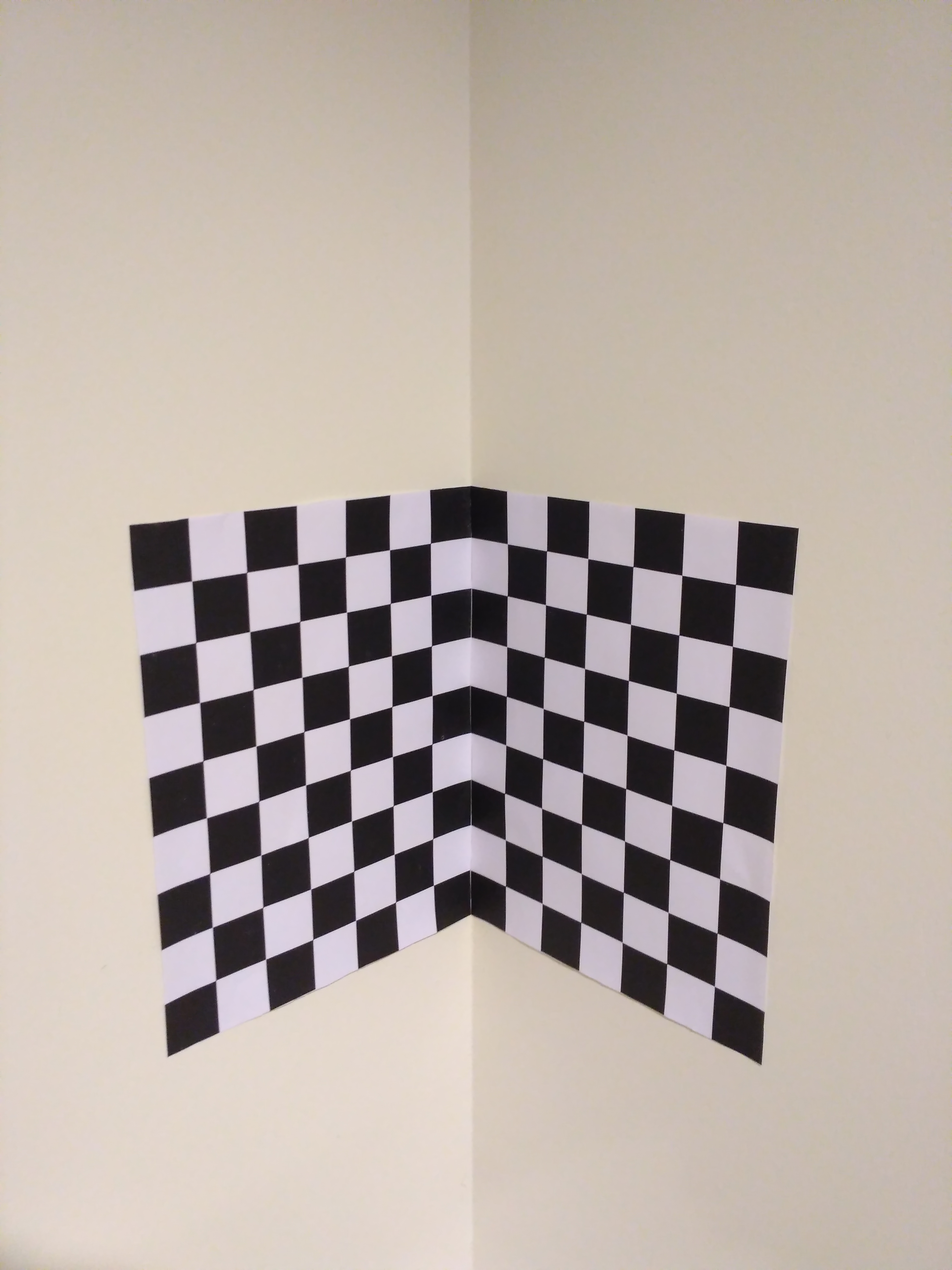
The aim of this homework was to calibrate a camera using a 3D calibration object which consists of two orthogonal checkerboard patterns and find the intrinsic and the extrinsic parameters of the camera.
1 Prepration
In the setup phase the checkerboard patterns were placed orthogonally for their photo to be taken. To be able to calibrate the camera both world coordinates and their image projections are needed, therefore a coordinate system was created to calculate the world coordinates.
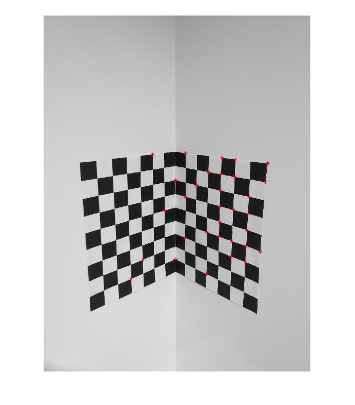
When the image is taken minimum eigenvalue corner detector was performed on the picture and 32 corners were selected. Since at least 6 points were needed (12 equations for 11 parameters) this was more than enough. Selected corners can be seen on the picture below:
Then the positions for this corners were measured with the world coordinate system that is just created. All world coordinates were measured in mm’s. Then the image coordinates and the world coordinates are pushed into two different vectors.
2 Calculating the Camera Matrix
After measuring scene Points Pi and their image correspondances pi, the aim is to find the camera matrix M.
Since we know that the product of camera matrix with the world coordinate gives us the image points we can create a homogenous system to solve for m1, m2 and m3 (which will make up M). 32 points taken created a 64 x 12 matrix for P and we got 12 x 1 for m.
To solve Pm = 0, the singular value decomposition can be used. If P = UVD in the singular value decomposition the column of V with the least eigenvalue will give us m. Therefore to compute V, the eigenvectors of matrix transpose(P) * P was found. Then the first column was taken, since it was the column with the least eigenvalue. After hving the 12 x 1 column of eigen vectors, the data was arranged in 3 x 4 format to consturct M.
3 Extracting intrinsic and extrinsic parameters
After constructing M, we can divide it in to 4 matrices A1, A2, A3 and B. A1 will be the first three columns of the first row, A2 will be the first three columns of the second row and A3 will be the first three rows of the third row. B will be the last column of M. Then if we say A = [A1; A2; A3] and A = KR where K is the intrinsic parameter matrix (3 x 3) and R is the rotation matrix (3 x 1) we can apply a RQ factorization.
f = (1/norm(A3)) * A3. e = A2 * transpose(R3) d = norm (A2 - e * R3) R2 = (1/d) * (A2 – e*R3) c = A1 * transpose(R3) b = A1 * transpose(R2) a = norm(A1 -(b * R2) - (c * R3)) R1 = (1/a) * (A1 -(b * R2) - (c * R3)) Then every element in the K matrix is divivded by f to make f variable 1 as in the original K matrix, since scale is not important. Since K and R is calculated, the only parameter that we need to know is the translation matrix and since T = inverse(K) * B, it was easily calculated , and the project was finished.
4 Results and Comparing
The results coming from my camera calibration:
Alpha = 3.523e+03 Beta = 3.555e+03 Uo = 1.619e+03 Vo= 1.961e+03 Theta = 1.57 rad ~ 86 deg SinTheta = 1 CosTheta = -0.0027 Skew = 9.5
The results coming from Caltech:
Focal Length: fc = [ 3970.47614 3781.47089 ] +/- [ 887.34111 360.09219 ] Principal point: cc = [ 1559.50000 2079.50000 ] +/- [ 0.00000 0.00000 ] Skew: alpha_c = [ 0.00000 ] +/- [ 0.00000 ] => angle of pixel axes = 90.00000 +/- 0.00000 degrees The results were not the same but they were pretty close.

