This repository contains all information regarding the code of Seeduino LoRaWAN and Adafruit Feather M0 Radio with LoRa Radio Module for the Pothole Detector project.
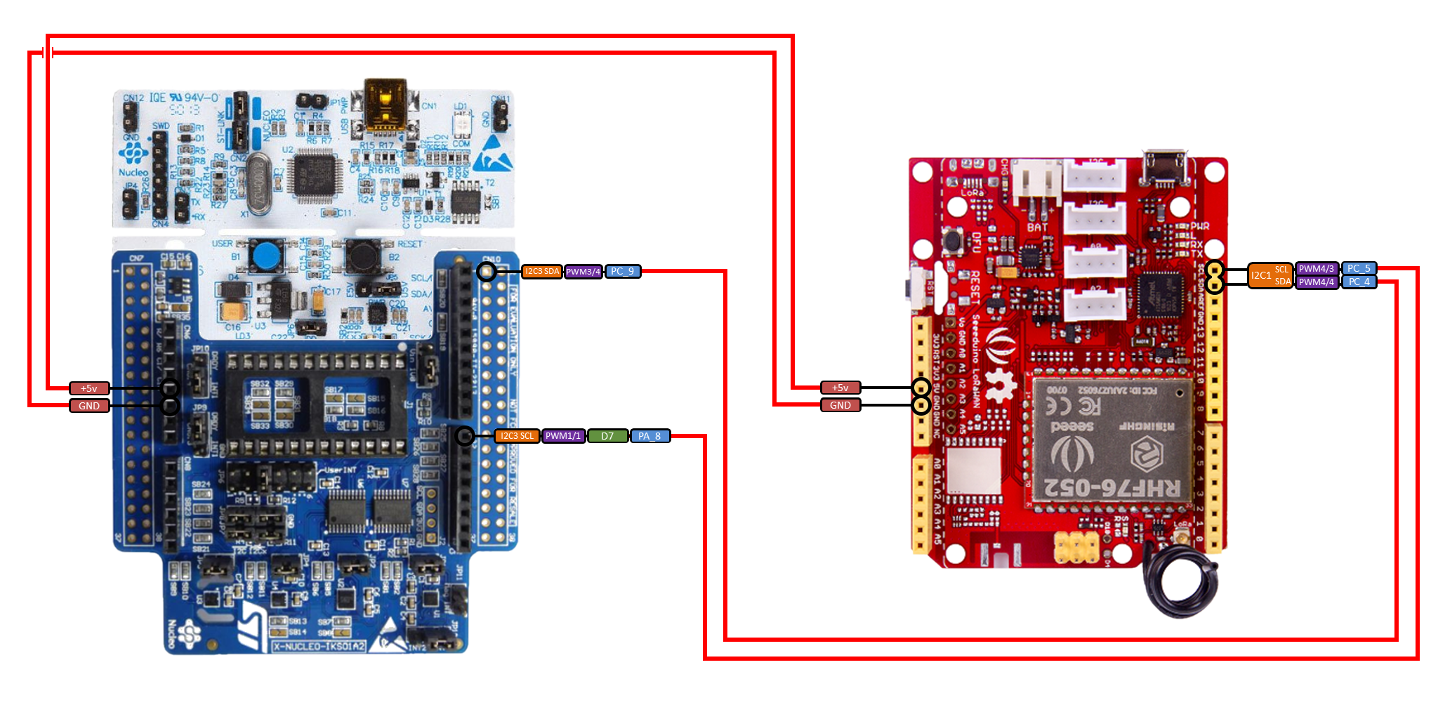
These board is part of a bigger system. The Seeduino LoRaWAN will be connected to the NUCLEO-F401RE board via I²C and it will send data through LoRa to the Adafruit Feather M0 Radio with LoRa Radio Module that is attached to a capable server with the node-serialport-reader.
The code sends via LoRa information regarding the position, date/time and the number of potholes detected by the NUCLEO board.
| Seeeduino LoRaWAN w/ GPS | STM32F401RE (X-NUCLEO-IKS01A2) |
|---|---|
| PC5 (SCL) | PA8 (I2C3 SCL) |
| PC4 (SDA) | PC9 (I2C3 SDA) |
| +5V | +5V |
| GND | GND |
Using the Android IDE you have to add the Additional Boards Manager URLs for the Seeduino and Adafruit boards into the Preferences section:
- https://adafruit.github.io/arduino-board-index/package_adafruit_index.json
- https://raw.githubusercontent.com/Seeed-Studio/Seeed_Platform/master/package_seeeduino_boards_index.json
Now you can download the board definition via the Boards Manager:
Seeduino SAMDfor the Seeduino boardAdafruit SAMDfor the Adafruit board
Upload the code to the devices (the same code works with both boards, it autodetects during compiling phase the right code to upload)
You will see on the serial monitor of the Seeduino all the messages received via I²C, the collected position with date and time via GPS and the message to send over the LoRa.
Because it is very difficult to take GPS position inside, there is a demo mode that uses constant positions in order to simulate a route.
Otherwise there is a fake mode that generates random positions in Rome around our departement, DIAG, you have only to change the value of the variable IS_GPS_DATA_FAKE inside the code.
The Seeduino LoRaWAN and the NUCLEO-F401RE are attached togher via I²C.
The Seeduino LoRaWAN board is set as a slave to the address 4 of the I²C bus.
Every time the NUCLEO-F401RE founds one (or with the Timed mode more then one) pothole, it sends the number of detection to the Seeduino LoRaWAN.
So for example for the following number of potholes detected in the Burst mode:
| Number of potholes |
|---|
| 2 |
The NUCLEO-F401RE will simply send:
2
The Seeduino LoRaWAN board, using an interrupt routine attached to the I²C bus, retrieves this number and, using its GPS capability, it fetches the position and the time of the occurred event. With all this information it creates a message that sends through the LoRa radio.
The Seeduino LoRaWAN and the Adafruit Feather M0 Radio with LoRa Radio Module are linked by a P2P LoRa communication link. In order to chat each other the two boards have to use the same configuration.
For our project we use the following configuration:
| Frequency (MHz) | Spreading Factor | Spreading Factor (chips/symbol) | Bandwidth (kHz) | Coding Rate | TX power |
|---|---|---|---|---|---|
| 433 | 6 | 128 | 125 | 4/5 | 20 |
N.B The use of the
433 MHzdepends on the state where you reside. In Italy (and in general in Europe) the free bands for use LoRa are433 MHzand868MHz.
In this way the two boards can listen each other but, in order to communicate, they must follow the same message protocol.
For our project we use a simple CSV format, and so, every value is divide by a , (comma).
latitude,longitude,date,time,number_of_potholes_detected
So for example for the following data:
| Latitude | Longitude | Date | Time | Number of potholes |
|---|---|---|---|---|
| 41.891004 | 12.50143 | 20/06/2018 | 20:15.10 | 2 |
The Seeduino LoRaWAN would produce the message:
41.891004,12.50143,20062018,201510,2
When the Adafruit Feather M0 Radio with LoRa Radio Module receives this message, it will immediatelly send over Serial in order to be parsed.
The Adafruit Feather M0 Radio with LoRa Radio Module uses the RadioHead Driver Library, the Seeduino LoRaWAN instead use AT commands over serial communication.
For further practical information about the LoRa protocol see the PingPong example in particular way the exaustive presentation about this technology using the Adafruit Feather M0 Radio with LoRa Radio Module board.
