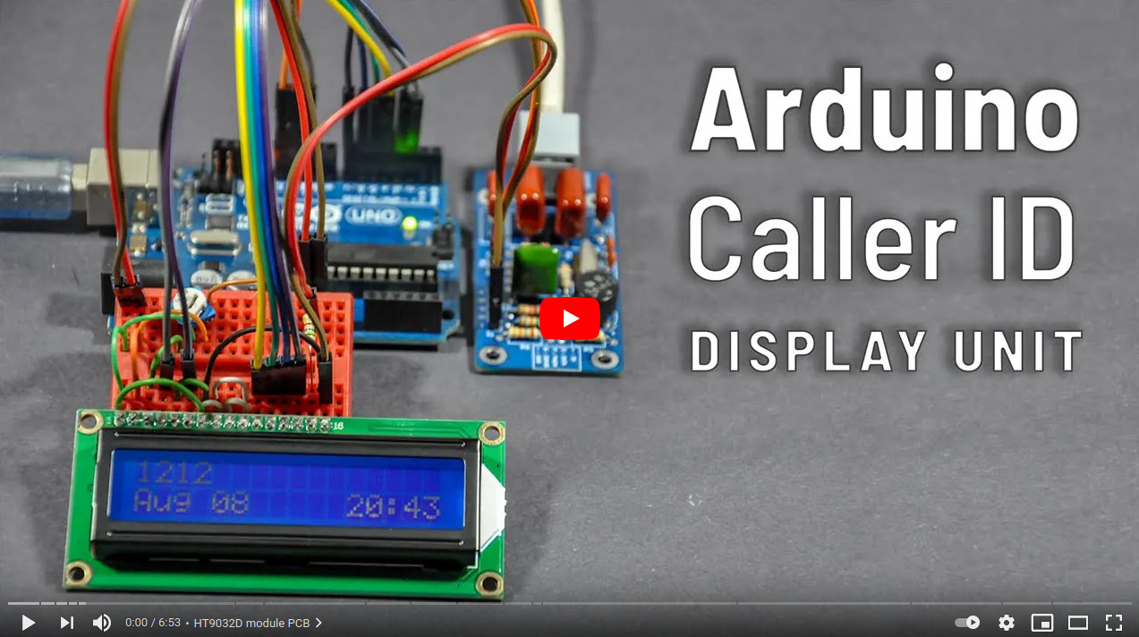
This project is a simple Caller ID (CLI) decoder made using the Arduino UNO and a custom-made HT9032D module.
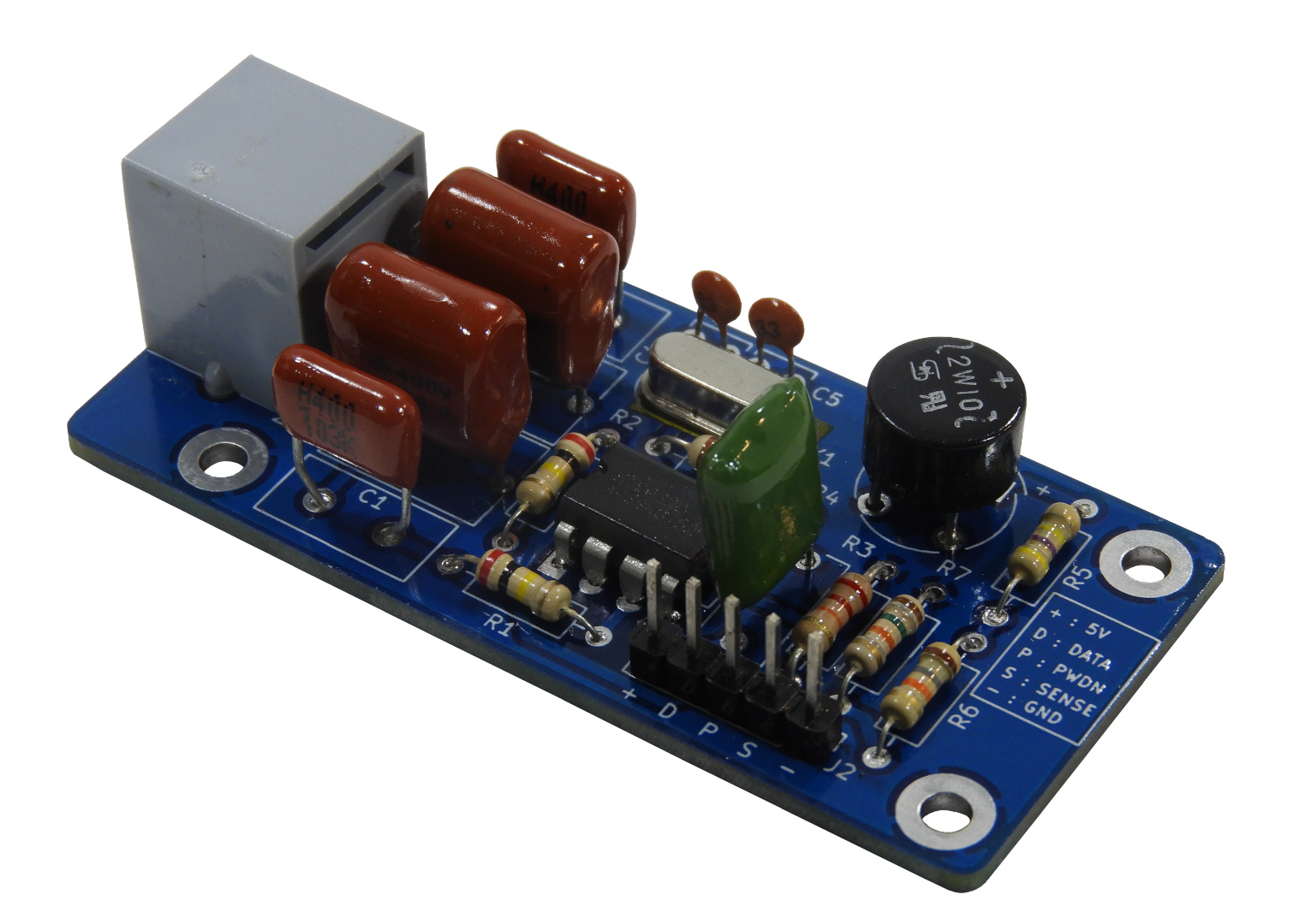
The HT9032D module design files are available at /ht9032d-module directory. Gerber files for PCB production are in the Release section of this repository.
The HT9032D module consists of standard through-hole type components. No special soldering equipment is needed to assemble this module.
The following table lists all the components needed to complete the HT9032D module.
| Designator | Value | Quantity |
|---|---|---|
| C1, C3 | 0.01μF / 400V | 2 |
| C2 | 0.1μF / 50V | 1 |
| C4, C5 | 33pF | 2 |
| C6, C7 | 0.22μF / 400V | 2 |
| D1 | 2W10 Bridge rectifier | 1 |
| R1, R2 | 200KΩ (¼W Carbon film resistor - 5%) | 2 |
| R3 | 22KΩ (¼W Carbon film resistor - 5%) | 1 |
| R4 | 10MΩ (¼W Carbon film resistor - 5%) | 1 |
| R5 | 470KΩ (¼W Carbon film resistor - 5%) | 1 |
| R6 | 18KΩ (¼W Carbon film resistor - 5%) | 1 |
| R7 | 15KΩ (¼W Carbon film resistor - 5%) | 1 |
| U1 | HT9032D (DIP-8) | 1 |
| Y1 | 3.58MHz (HC49) Crystal | 1 |
| J1 | RJ11 / 6P6C, 6-pin, right angle, PCB socket (Molex 52018-6616 or equivalent) | 1 |
| J2 | 5-pin 2.54mm Pin header | 1 |
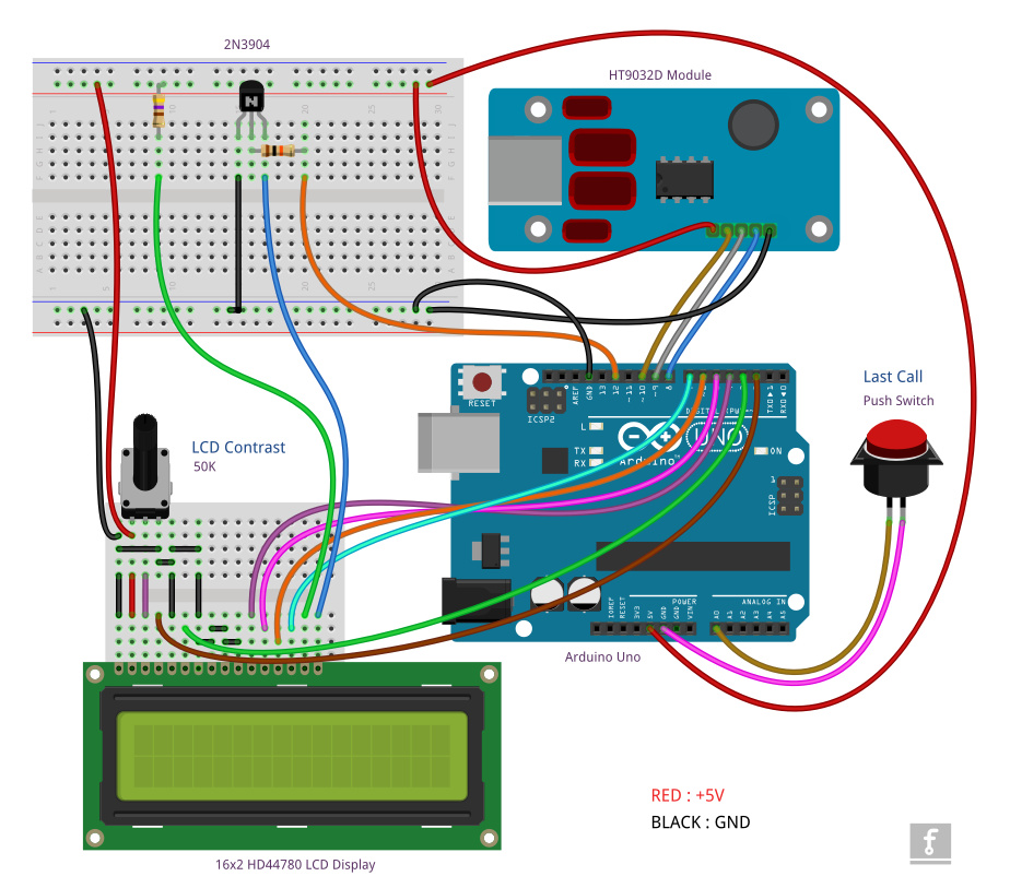
The following components and modules are required to assemble the call ID display unit.
- Assembled HT9032D module
- Arduino UNO board
- 16x2 HD44780 character LCD panel
- 2N3904 (or equivalent NPN) Transistor
- 50KΩ Trimpot (RM-063 or equivalent)
- 560Ω (¼W) resistor
- 22KΩ (¼W) resistor
- Few mini/small breadboard(s)
Both pictorial and symbolic wiring diagrams are provided to minimize the complexity of assembly.
The Arduino sketch required for this caller ID is available here.
The current version of this caller ID decoder sketch can handle the caller line ID, name, and date/time MDMF (Multiple Data Message Format) packet IDs only.
All the source codes in this repository are released under the terms of the MIT License. The HT9032D module design files are released under the CERN-OHL-W Version 2.0 License.


