Arduino on Pi boards, the best of both worlds !


![]()
![]()
PiDuino is a C ++ library for Pi boards that allows the use of I/O like GPIO,
I2C, SPI, UART ... with an API as close as possible to the Arduino language.
The description of Pi cards uses a stored "Object" model in a database that
allows to add new models of boards easily.
This approach allows you to compile libraries normally intended for Arduino, for example, Radiohead. Normally, all libraries that do not use the specificities of a target microcontroller should be able to compile. There is a tutorial explaining how to do this, in French, but Google will translate it into your language...
At this time, the SoC models supported are AllWinner H-Series and Broadcom BCM2708 through 2712 which allows it to be used on Raspberry Pi and most Nano Pi, Orange Pi and Banana Pi.
The updated list of all the boards in the database is available in the
Wiki.
Note that if the revision number of your Raspberry Pi board is not in the database, piduino will use this number to find the same model boards in the database to make the right settings.
To learn more about PiDuino, you can follow the Wiki, but if you're in a hurry, let's go to the quick start version...
The fastest and safest way to install piduino on Armbian is to use the APT repository from piduino.org, so you should do the following :
wget -O- http://www.piduino.org/piduino-key.asc | sudo gpg --dearmor --yes --output /usr/share/keyrings/piduino-archive-keyring.gpg
echo "deb [signed-by=/usr/share/keyrings/piduino-archive-keyring.gpg] http://apt.piduino.org $(lsb_release -c -s) piduino" | sudo tee /etc/apt/sources.list.d/piduino.list
sudo apt update
sudo apt install libpiduino-dev piduino-utils
This repository provides Piduino packages for armhf and arm64 architectures for buster, bullseye, and bookworm distributions.
If you want to build from sources, you can follow the Wiki.
Once installed, you should run the following on the command line :
$ pinfo
Name            : NanoPi Core2 Mini Shield
Family          : NanoPi
Database Id     : 40
Manufacturer    : Friendly ARM
Board Tag       : nanopineocore2shield
SoC             : H5 (Allwinner)
Memory          : 1024MB
GPIO Id         : 9
I2C Buses       : /dev/i2c-0
SPI Buses       : /dev/spidev1.0
Serial Ports    : /dev/ttyS1
As we can imagine, in the example, we are on a NanoPi Neo Core2 connected to a Mini Shield.
To read the pin status of connector 1, run the following on the command line :
$ pido readall 1
                                          CON1 (#1)
+-----+-----+----------+------+------+---+----++----+---+------+------+----------+-----+-----+
| sOc | iNo |   Name   | Mode | Pull | V | Ph || Ph | V | Pull | Mode |   Name   | iNo | sOc |
+-----+-----+----------+------+------+---+----++----+---+------+------+----------+-----+-----+
|     |     |     3.3V |      |      |   |  1 || 2  |   |      |      | 5V       |     |     |
|  12 |   8 |  I2C0SDA | ALT2 |  OFF |   |  3 || 4  |   |      |      | 5V       |     |     |
|  11 |   9 |  I2C0SCK | ALT2 |  OFF |   |  5 || 6  |   |      |      | GND      |     |     |
|  91 |   7 |  GPIOG11 |  OFF |  OFF |   |  7 || 8  |   | OFF  | ALT2 | UART1TX  | 15  | 86  |
|     |     |      GND |      |      |   |  9 || 10 |   | OFF  | ALT2 | UART1RX  | 16  | 87  |
|   0 |   0 |   GPIOA0 |  OFF |  OFF |   | 11 || 12 |   | OFF  | OFF  | GPIOA6   | 1   | 6   |
|   2 |   2 |   GPIOA2 |  OFF |  OFF |   | 13 || 14 |   |      |      | GND      |     |     |
|   3 |   3 |   GPIOA3 |  OFF |  OFF |   | 15 || 16 |   | OFF  | ALT2 | UART1RTS | 4   | 88  |
|     |     |     3.3V |      |      |   | 17 || 18 |   | OFF  | ALT2 | UART1CTS | 5   | 89  |
|  15 |  28 | SPI1MOSI | ALT2 |  OFF |   | 19 || 20 |   |      |      | GND      |     |     |
|  16 |  24 | SPI1MISO | ALT2 |  OFF |   | 21 || 22 |   | OFF  | OFF  | GPIOA1   | 6   | 1   |
|  14 |  29 |  SPI1CLK | ALT2 |  OFF |   | 23 || 24 |   | OFF  | ALT2 | SPI1CS   | 27  | 13  |
|     |     |      GND |      |      |   | 25 || 26 |   | OFF  | OFF  | GPIOA17  | 11  | 17  |
+-----+-----+----------+------+------+---+----++----+---+------+------+----------+-----+-----+
| sOc | iNo |   Name   | Mode | Pull | V | Ph || Ph | V | Pull | Mode |   Name   | iNo | sOc |
+-----+-----+----------+------+------+---+----++----+---+------+------+----------+-----+-----+
pido and pinfo come with manpages...
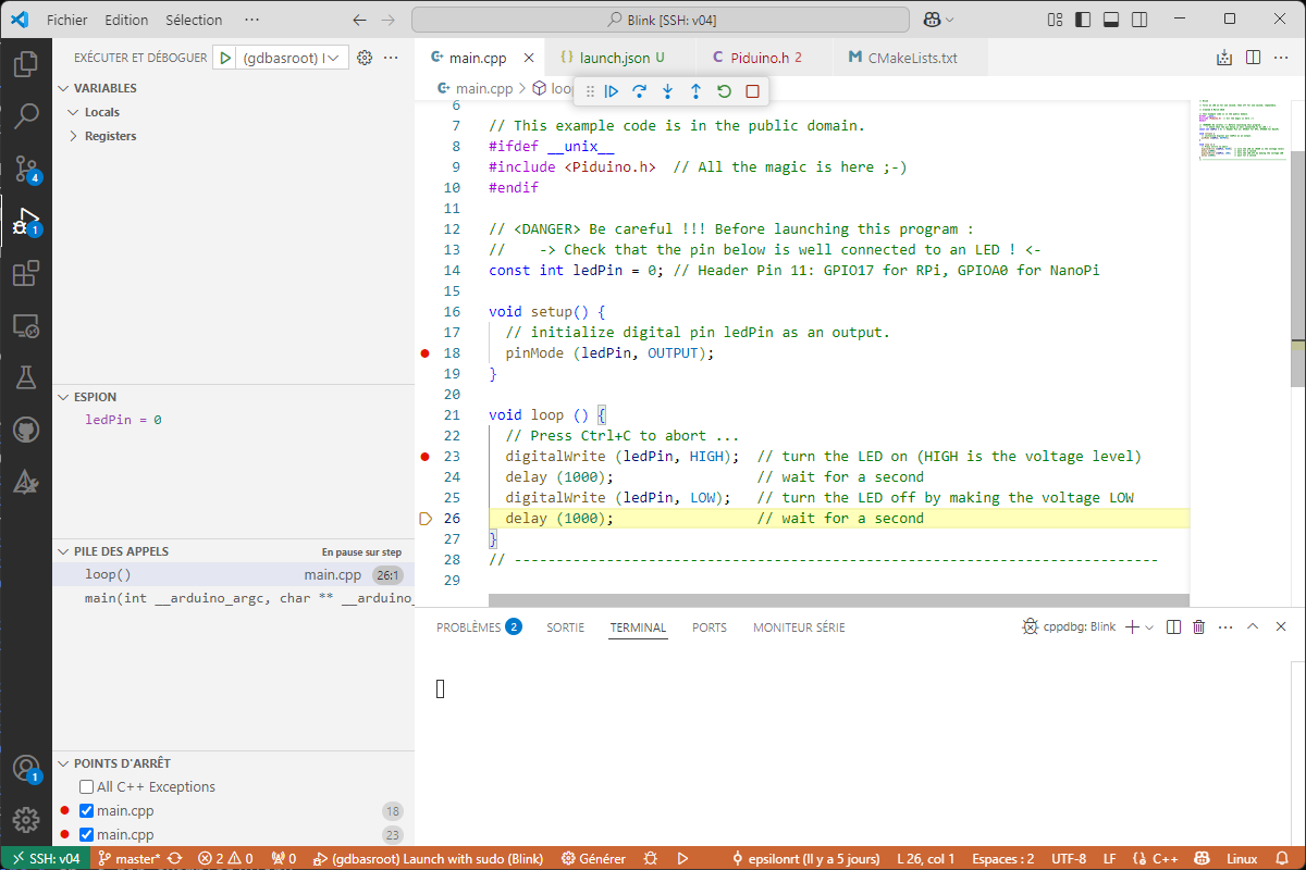
Arduino programming on Pi board ? We are going there !
#include <Piduino.h> // all the magic is here ;-)

const int ledPin = 0; // Header Pin 11: GPIO17 for RPi, GPIOA0 for NanoPi

void setup() {
  // initialize digital pin ledPin as an output.
  pinMode (ledPin, OUTPUT);
}

void loop () {
  // Press Ctrl+C to abort ...
  digitalWrite (ledPin, HIGH);  // turn the LED on (HIGH is the voltage level)
  delay (1000);                 // wait for a second
  digitalWrite (ledPin, LOW);   // turn the LED off by making the voltage LOW
  delay (1000);                 // wait for a second
}
Obviously, you need to know the pin number where you connected the LED !
$ pido readall 1
                                          CON1 (#1)
+-----+-----+----------+------+------+---+----++----+---+------+------+----------+-----+-----+
| sOc | iNo |   Name   | Mode | Pull | V | Ph || Ph | V | Pull | Mode |   Name   | iNo | sOc |
+-----+-----+----------+------+------+---+----++----+---+------+------+----------+-----+-----+
|     |     |     3.3V |      |      |   |  1 || 2  |   |      |      | 5V       |     |     |
|  12 |   8 |  I2C0SDA | ALT2 |  OFF |   |  3 || 4  |   |      |      | 5V       |     |     |
|  11 |   9 |  I2C0SCK | ALT2 |  OFF |   |  5 || 6  |   |      |      | GND      |     |     |
|  91 |   7 |  GPIOG11 |  OFF |  OFF |   |  7 || 8  |   | OFF  | ALT2 | UART1TX  | 15  | 86  |
|     |     |      GND |      |      |   |  9 || 10 |   | OFF  | ALT2 | UART1RX  | 16  | 87  |
|   0 |   0 |   GPIOA0 |  OFF |  OFF |   | 11 || 12 |   | OFF  | OFF  | GPIOA6   | 1   | 6   |
|   2 |   2 |   GPIOA2 |  OFF |  OFF |   | 13 || 14 |   |      |      | GND      |     |     |
|   3 |   3 |   GPIOA3 |  OFF |  OFF |   | 15 || 16 |   | OFF  | OFF  | GPIOG8   | 4   | 88  |
|     |     |     3.3V |      |      |   | 17 || 18 |   | OFF  | OFF  | GPIOG9   | 5   | 89  |
|  22 |  12 |   GPIOC0 |  OFF |  OFF |   | 19 || 20 |   |      |      | GND      |     |     |
|  23 |  13 |   GPIOC1 |  OFF |  OFF |   | 21 || 22 |   | OFF  | OFF  | GPIOA1   | 6   | 1   |
|  24 |  14 |   GPIOC2 |  OFF |  OFF |   | 23 || 24 |   | UP   | OFF  | GPIOC3   | 10  | 25  |
+-----+-----+----------+------+------+---+----++----+---+------+------+----------+-----+-----+
| sOc | iNo |   Name   | Mode | Pull | V | Ph || Ph | V | Pull | Mode |   Name   | iNo | sOc |
+-----+-----+----------+------+------+---+----++----+---+------+------+----------+-----+-----+
The iNo column corresponds to the 'Arduino' number, the number 0 pin corresponds therefore at pin 11 of the GPIO connector (GPIOA0).
To build, you must type the command:
$ cd examples/Blink
$ mkdir build
$ cd build
$ cmake ..
$ make
You can then execute the program :
$ sudo ./Blink
sudo is necessary for an access to the memory mapping of the GPIO).
You can enable the setuid bit to avoid sudo in the future :
$ sudo chmod u+s Blink
$ ./Blink
It is possible to use Visual Studio Code for development with a SSH connection, but you have to install the CMake Tools plugin and CMake (version 3.10 or higher).
You can use the examples/Template folder and the Project Templates extension to simplify project creation.
It is also possible to use Codelite it's easier and funny, right ?
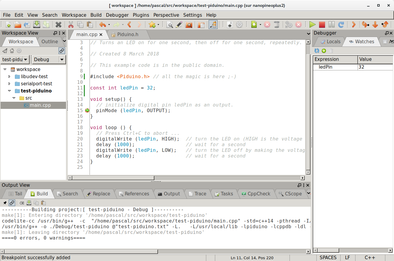
You should read the wiki on the examples to learn more...
Since version 0.7, Piduino has supported a unified conversion system for sensors and actuators. This includes classes for ADCs, DACs, and GPIO expanders, allowing for easy integration of I2C and SPI peripherals. This is made possible by a modular and extensible architecture and the Converter class.
The Converter class provides a unified interface for interacting with various analog and digital converters such as ADCs, DACs, and GPIO expanders. This powerful abstraction layer allows seamless integration of I2C and SPI peripherals like the MAX1161x series ADCs, MCP4725/MCP4728 DACs, and MAX7311 GPIO expanders. The converter system supports automatic device detection, multiple reference voltages, differential measurements, and configurable resolution settings.
The list of supported converters can be found with the pido utility:
$ pido converters
Name                Type      Parameters
--------------------------------------------------------------------------------
gpiopwm             dac       pin[:range:freq]
max1161x            adc       bus=id:max={12,13,14,15,16,17}:ref={ext,vdd,int1,int2,int3,int4}:fsr=value:bipolar={1,0}:clk={int,ext}
max7311             gpioexp   bus=id:addr={0x20...0xDE}:bustimeout={0,1}
mcp4725             dac       bus=id:addr={0x60..0x67}:fsr=value:mode={norm,fast,eeprom,pd1k,pd100k,pd500k}
mcp4728             dac       bus=id:addr={0x60..0x67}:ref={vdd,int}:fsr=value:gain={1,2}:mode={norm,fast,eeprom,pd1k,pd100k,pd500k}
For the moment, the list is relatively short, but it should grow over time.
You can easily control converters from the command line using the pido utility. For example, to read an analog value from channel 0 of a MAX11615 ADC connected to I2C bus 1:
$ pido -c max1161x:bus=1:max=15:ref=int4 cread 0
1843

$ pido -c max1161x:bus=1:max=15:ref=int4 -m cread 0
1.502V
The same functionality is available in C++ code using the converter factory system:
#include <Piduino.h>
#include <Converters.h>

// Create a MAX11615 ADC instance with the factory method
std::unique_ptr<Converter> adc (Converter::factory ("max1161x:bus=1:max=15:ref=int4"));

void setup() {

  Console.begin (115200);

  if (!adc->open()) {
    Console.println ("Failed to open ADC");
    exit (EXIT_FAILURE);
  }
}

void loop() {
  // Read digital value from channel 0
  long digitalValue = adc->readChannel (0);

  // Convert to analog voltage
  double voltage = adc->digitalToValue (digitalValue);

  Console.print ("Channel 0: ");
  Console.print (digitalValue);
  Console.print (" (");
  Console.print (voltage);
  Console.println ("V)");

  delay (1000);
}