-
-
Notifications
You must be signed in to change notification settings - Fork 113
Switch Board
In order to have more power over the behavior of the console, some changes are sometimes necessary. The currently most popular change that involves the PIO port is the installation of a Switch Board for the PSIO cart. We are also proposing a second modification that also involves the PIO port.
The PSIO cart is emulating the CD-Rom controller of the PlayStation. Thus it requires two signals from the motherboard: !CS5 and !IN2. These are the Chip Select and Interrupt lines of the CD-Rom controller respectively. Since the CD-Rom controller is connected on the same bus, no other signal are required to be redirected.
The idea behind cybdyn's Switch Board is that it acts as a physical dual pole double throw (http://www.learningaboutelectronics.com/Articles/Double-pole-double-throw-switch-DPDT) switch. When the PSIO cart isn't plugged in, or when the PSIO is disabled, the "EN" signal of the Switch Board is asserted low using a pull down resistor. In this mode, the !CS5 and !IN2 signals from the CD-Rom controller are connected to the PSX CPU. When the "EN" signal is asserted high, then the PSX CPU !CS5 and !IN2 are connected to the PIO's pins 65 and 31 respectively.
The Switch Board schematics are fairly straightfoward to understand:
Thus, the PIO Breakout board indicates pins 31 and 65 as !CS5 and !IN2 respectively.
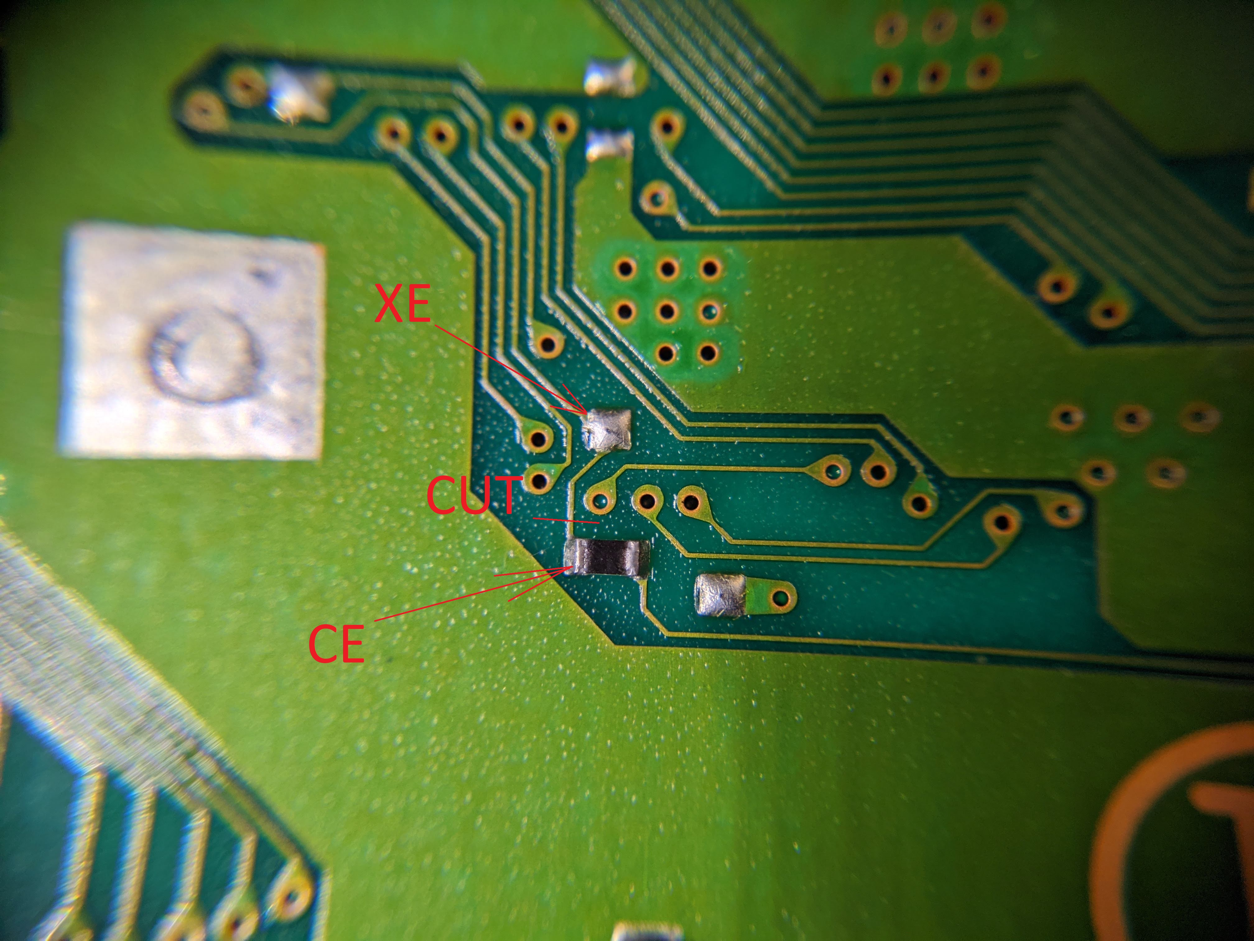
In order to replace the BIOS of the machine from the PIO port, a similar modification is required. One would need to cut the BIOS' !CS2 line in order to connect it to a Switch Board and to the PIO port. This means that the PIO line 39 is then becoming this !CS2 signal.
Here are some installation instructions for the PU-18 PCB. More research would be necessary to provide similar instructions for other versions, but to identify the !CS2 line, it's on pin 22 of the 32 pins IC102 BIOS chip, and there's supposed to be an inline resistor between the rom chip and the CPU, intended to slow the signal down ever so slightly.
Location of the CS2 line on the overall PU-18 motherboard:

Zoomed into this location, with the cut to make and the solder points to the Switch Board:

PIO lines to solder and cut:

Overall installation picture:

With the installation above, it becomes technically impossible to hook both into the bios, and still be able to use the PSIO cart. The solution to this conundrum however can be simply to install two Switch Board, and a SPDT switch to flip the EN line between the two. Since the Switch Board has a pulldown on its EN pin, only one of them will be active at a single time.
