Triggered Activation of a Simulink Subsystem
We need to drive (trigger) the execution of Subsystem blocks at specific time steps, including zero (t=0, i.e., the beginning of the simulation). The most natural solution seems to be the use of Triggered Subsystems. However, this does not work at t=0, since the "edge" that triggers a Subsystem is, by definition, computed onto two samples. Solving this issue is not trivial.
There are three approaches that have been proposed on Matlab Answers to address this problem:
- Use Function-Call Generators and Function-Call Subsystems instead of Triggered Subsystems;
- Use Stateflow Charts instead of Function-Call Generators, to allow complex connections among Function-Call Subsystems;
- Use a Detect Increase Block connected to an Enabled Subsystem.
The problem with (1) is that it works only with specific set-ups. The function-call mechanism is "fragile" and you can easily run into function-call dependency violations. See e.g.: https://github.com/m-morelli/tres_bundle/issues/2
Solution (2) greatly helps to solve these issues, but at expenses of requiring an additional MathWorks product to manage the activation logics. If possible, we would like to solve the problem using only the basic capabilities offered by Simulink, without any additional product (this also excludes the use of SimEvents).
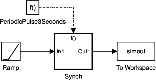
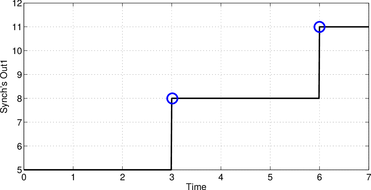
Method (3) as proposed is wrong. Consider an Enabled Subsystem that samples the output of a Ramp block every 3 seconds (the Ramp output is 5 at t=0). The following diagram implements method (3) as proposed on Matlab Answers.
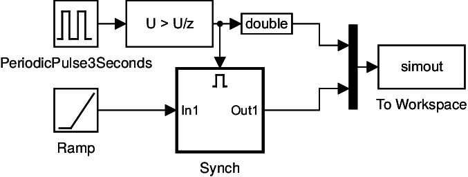
Synch realizes the sampling. It is an empty Subsystem with just the input and the output ports connected. The Ramp output is in fact sampled at t=0 and every 3 seconds, but the output is different from what is expected. In particular, we don't want that the portion of the Ramp output circled in red be in the output of the Enabled Subsystem. We wouldn't have that piece of signal if we were using a Function-Call-based sampler.
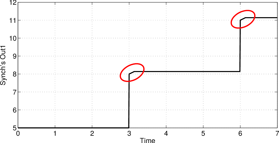
The problem is caused by a misuse of the semantics of the Enabled Subsystem, which, by definition, enables the flowing of data between the time steps in which the state changes from enabled (time steps 3, 6, and so on) to not enabled (3+one time step, 6+one time step and so on).
We propose a solution based on (3). In our method, the Subsystem to be activated at precise time steps (Synch in the above example) is enclosed into a Function-Call Subsystem, whose semantics fits well for this purpose. To break any eventual dependency loop with the activator, the Function-Call Subsystem is put inside an Enabled Subsystem, which is driven by a Detect Increase Block as proposed in (3). An S-Function is implemented that acts like a Enable-to-Function-Call converter, and is put inside the Enabled Subsystem to drive the Function-Call block. This also "modifies" the semantics of the Enabled Subsystem to comply with Function-Call (with the already mentioned advantage of breaking any eventual function-call dependecy loop, which was the problem of method (1)). The previous example implemented according to our method is like this
(a)
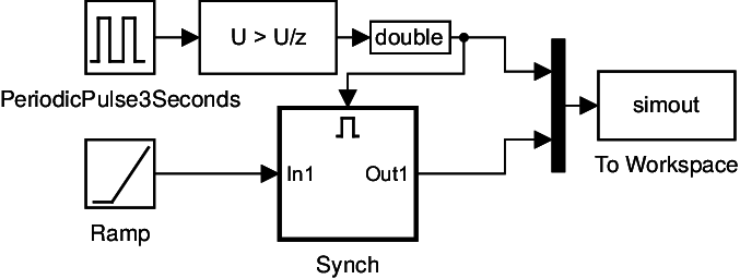
(b)
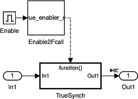
where (b) represents the content of Synch in (a) and TrueSynch is the empty Subsystem that actually realizes the sampler. The results are as expected
The proposed method solves the issue and is semantically equivalent to method (1), represented below (except for the larger number of evaluated time steps)