-
Notifications
You must be signed in to change notification settings - Fork 28
Build and upload
-
Clone the project from GitHub
-
Open it with Visual Studio Code
-
Install the PlatformIO extension
-
Click the build icon in the status bar
The ZY12PDN board has 4 pads for SWD at the bottom.

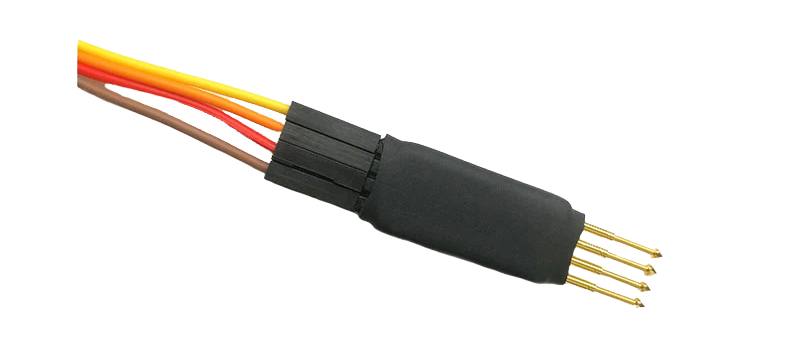
Either solder wires to them, or use a 4-pin adapter with pogo pins to connect a debug adapter such as ST-Link, J-Link or Black Magic Probe.

Connect the debug adapter to your computer and click the upload icon in the status bar of Visual Studio Code.
If your debug probe does not provide power to the ZY12PDN board, it needs to be supplied differently to upload the firmware successfully. The options are:
- Feed power to the USB connector from a non USB PD power supply
- Feed 3.3V to the VCC pad on the bottom side of the board
- Feed 5V to the output terminal
Do not connect a USB PD power supply during firmware upload. There is a conflict between the FUSB302 interrupt line and the SWDIO line. SWD and thus firware uploads stop working as soon as the firmware detects a USB PD power source.
As sold, some of the boards have flash protection enabled. It can be disabled using openocd. Note: This command erases the flash memory.
openocd -f interface/stlink.cfg -f target/stm32f0x.cfg -c "init; reset halt; stm32f0x unlock 0; stm32f0x mass_erase 0; reset halt; exit"
If the board can no longer be flashed with the SWD connector on the back side because the firmware cannot stop the PD controller from interfering with the SWDIO line, the board can be revived like so:
-
Solder a wire to NRST. The easiest location for soldering is capacitor C6 (on the left side of the capacitor, see components).
-
Connect all four SWD pins plus NRST to a debug adapter.
-
Use a firmware upload/erase configuration that connects under reset.
-
Erase the flash.
This successfully works with a J-Link adapter or a J-Flash Lite (but not with J-Flash). An ST-Link adapter and the proper configuration might also work.