Prerequisites
Important
Make sure to use a stable power supply, avoid using a Macbook as they generally don’t supply enough current and results in unexpected behavior of the ESP32 and/or PN532.
Tip
Recommend soldering the wires as the DuPont connectors may cause connectivity issues
Make sure you have the following ready:
-
A development board with an ESP32 chip, any board should be fine as long as it has an ESP32, ESP32-C3 chip
-
A PN532 NFC Module
- The SPI protocol needs to be used
- For the red board from Elechouse(or clones), there should be a DIP Switch on it and a small table to the side that indicates the switches states for each protocol, for SPI this should be 0 and 1 which means left ⬅️ switch down ⬇️ and right ➡️ switch up ⬆️
- Avoid using long wires between the PN532 and ESP32 or you’ll run into stability issues or connectivity issues
- The SPI protocol needs to be used
Tip
There are some custom PCB boards designed by the community that incorporate an ESP32 and a PN532
-
@lollokara did a really nice one with support for an external NFC antenna, RGB LED and 48V input(alongside USB-C), files can be found here and is available to be ordered from PCBWay directly here, though it is a bit pricey (~€70, outsourcing is expensive on such low scale)
-
@darkside9009 also did one with an integrated NFC antenna, it's not open-source, but the board can be ordered from Amazon here
Note
Most PN532 boards that you find online will either have low quality components and/or straight up non-genuine IC, see Buyer’s Guide below
Important
Information given here won’t guarantee that what you bought will be 100% without issues but hopefully will at least get you on the right path for a better part.
If you choose to buy from AliExpress, make sure to check the reviews and photos from customers as some vendors post photos that don’t reflect reality.
While it would be easier to post some links where to buy, things can change, product might get delisted, go out of stock or the vendor might change the supplier to a lower quality one, therefore I believe it would best if you know how to choose the better part from the vast choices there are.
Important
It should be known that all boards that cost around 4-5€ or under are using non-genuine IC, the PN532 IC alone costs around 5€ and we still have the other things to account for, even with bulk discount it wouldn’t be economically viable, but hopefully this helps you pick the better clone.

Warning
You’ll mostly find boards with these two black components, they are ferrite beads, those are still inductors but they have different properties, are used in other types of circuits and are not suited to be used in impedance matching which results in an inefficient antenna.
While shopping for a PN532, check the pictures to see if it has these two blueish components, those are wire-wound inductors that are used for impedance matching, essential for an efficient power transfer to the antenna.

Note
These boards might still use low quality components but should have a range of about 3-4cm and be slightly more reliable.
You also have the option to buy from Elechouse, they have quality stuff but it’s more pricey.
Elechouse is the original designer for the red boards you see everywhere as the schematic and board drawing for their PN532 NFC RFID MODULE V3 is public but they no longer sell it instead they released the V4.
You can find the PN532 NFC RFID MODULE V4 only on their official website here
Generally any board you get should be fine, however, it is worth noting that most have non-genuine modules (the little board with metal casing) and some have cheap flash chips with low flash endurance which leads to a shorter lifespan. Unfortunately there is no real way of telling which is the better clone.
Typically genuine modules will have “ESPRESSIF” etched on the metal casing along with their logo(though wouldn’t rely on it), however, as with the PN532, you might encounter vendors that are not posting representative pictures. Make sure to check the reviews.
Tip
Genuine development boards can be ordered from any of the major distributors like Mouser or Digikey
Warning
Both the ESP32 and the PN532 have to be using the same power supply otherwise they won’t be able to communicate.
The pins used can be changed from WebUI, however, the default pinout follows the Arduino defaults for SPI and for an ESP32 it is as following:
| ESP32 Pin | <-> | PN532 Pin |
|---|---|---|
| VCC/3V3 | <-> | VCC* |
| GND | <-> | GND |
| GPIO18 | <-> | SCK |
| GPIO19 | <-> | MISO |
| GPIO23 | <-> | MOSI |
| GPIO5 | <-> | SS |
Tip
See below for default pinout on other ESP32 variants
1. MH-ET D1 Mini (ESP32)
Related SPI pins are located here

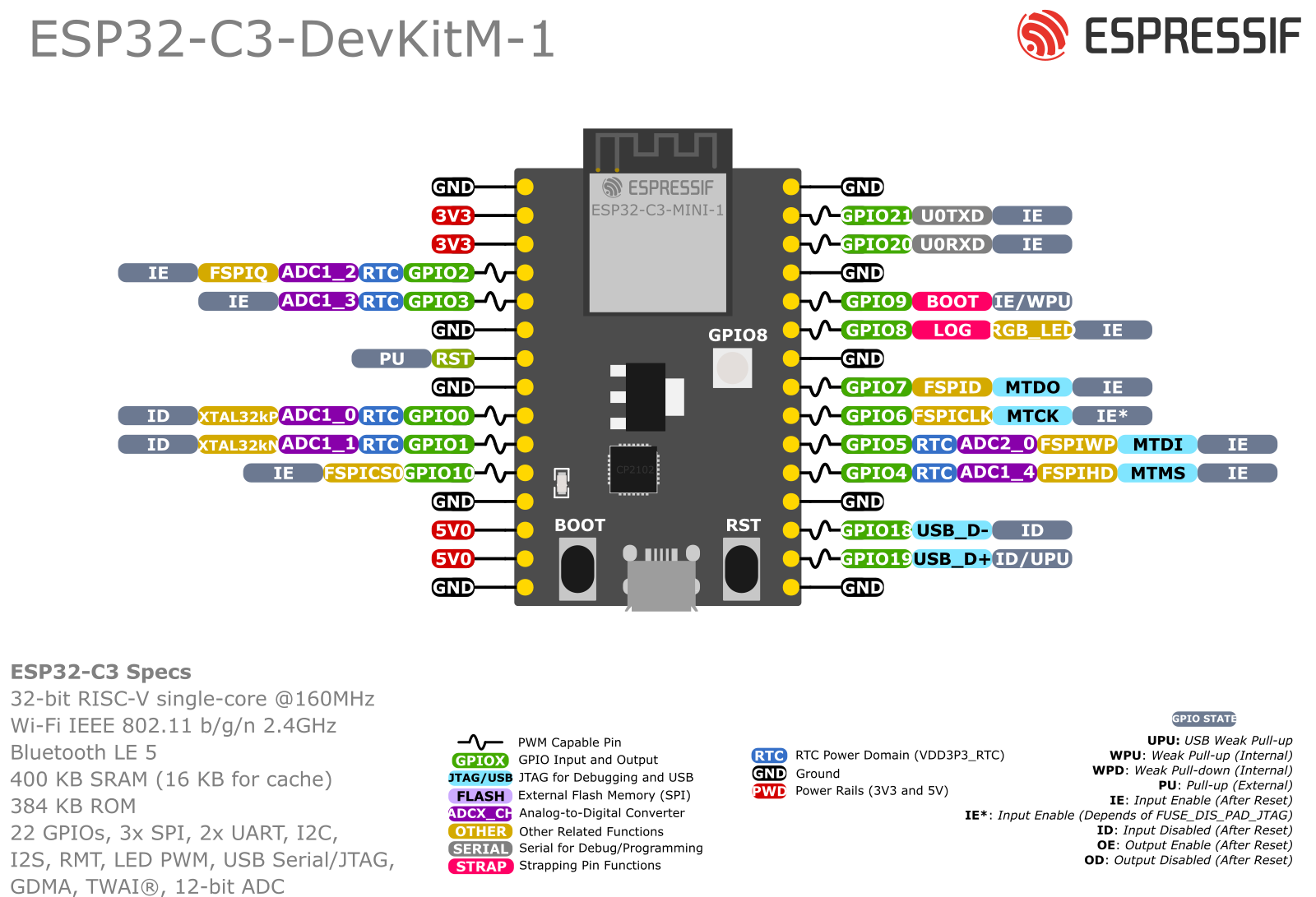
2. ESP32-C3-DevKitM-1 (ESP32-C3)
Related SPI Pins are
- SS: GPIO7
- SCK: GPIO4
- MISO: GPIO5
- MOSI: GPIO6