
This project is inspired by the work of many others who successfully managed to replace the hardware bridge from Zehnder called "Comfoconnect LAN C" by an ESP32 + CAN transceiver, namely those ones in particular : https://github.com/vekexasia/comfoair-esp32 & https://github.com/dardhal/comfoair-esp32 and leveraging the excellent work from Michael Arnauts on mapping the CAN frames : https://github.com/michaelarnauts/aiocomfoconnect
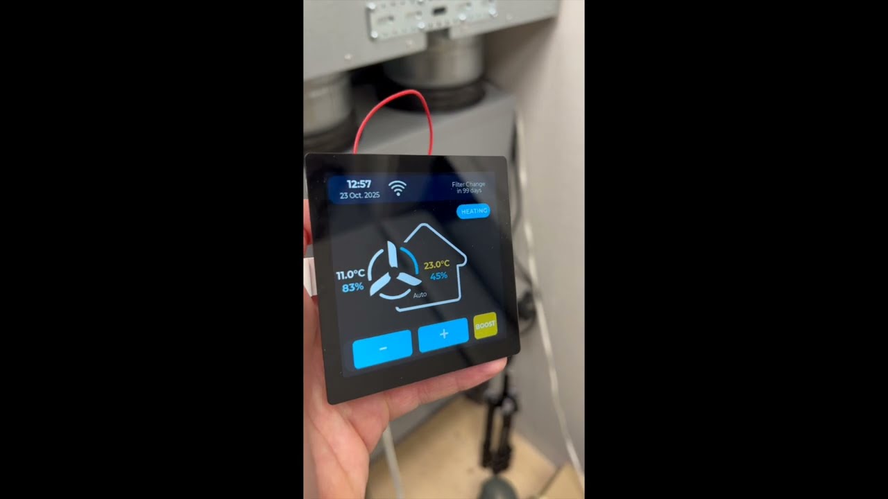
This new device is meant to not only replace the ComfoConnect LAN but also the ComfoSense controller display which is the default display typically installed in the house to interact with the ComfoAir. On top of having a much better UI, it's been optimized to be very snappy and responsive.
This device can function in two modes: Directly connected to the ComfoAir, in place of the ComfoSense or as a Remote Client.
Remote Client requires a simpler MQTT bridge, using the same firmware with slightly different settings


Demo of the device
Demo ComfoSense Touch (2min - Youtube)
ComfoSense C67 in comparison

This version has the following features and tackle the issues below:
1. Wifi connection close to the Comfoair can be limited due to its location (typically the attic or the cellar), hence bringing the IoT device closer to a central area in the house (where the ComfoSense display controller normally sits) mitigate this.

2. Better user interface than the one ComfoSense, with all basic functions exposed in one screen

3. Provides exact number of days before filter change is needed (instead of the generic message Expect change of filter soon ... for 3 weeks)

4. Provides additional sensor data coming from the MVHR (temperature, humidity)

5. Provide same integration with HomeAssistant via MQTT, similarly to the original ESP32 + CAN Transceiver program
This means this display can be used also by people who are not interested in the HA integration but simply want a better UI/UX than the one provided by Zehnder
-
Specifically the Waveshare ESP32S3 4 inch Touch display Dev Board (contains an embedded CAN transceiver): https://www.waveshare.com/wiki/ESP32-S3-Touch-LCD-4 Watchout that Waveshare also has a 4.3in device which wouldn't work for this project, both from a power and lack of CAN transceiver pov.
-
Optionnally: two SMD resistors, size 0402 (0R or a wire and a 100k value) in order for the dimming feature to work (see Dimming section for more details.)
-
For the Bridge, this device is ideal: https://www.waveshare.com/esp32-s3-rs485-can.htm . This firmware is fully compatible with it and requires few adjustments of the PINs in twai_wrapper and main.cpp to be fully functional.
First, rename the "secrets_template.h" file at the top of this repository into "secrets.h" and fill in the configuration: Wifi, MQTT config, Night Time Mode, Dimming, Timezone
In platformio.ini, set the path to your device (by default it is /dev/cu.usbmodem1101).
Then compile the code using PlatformIO:
pio run -t clean
pio run -e esp32s3
pio run -t upload -e esp32s3
pio device monitor -b 115200
That's it ! Check further below for the mounting bracket to install it on the wall and options for dimming the screen (requires hardware changes)
Important
When printing the decorating frame, consider scaling it up to 100.2% along the X and Y axis. This is already modified in the 3mf file. Otherwise it's a little bit tight to install and you could damage the screen when putting it on or off (the edges crack easily)
The mounting consists of 3 main part : two oversized (150%) Garmin style mount (male and female) and a decorative frame fixed by friction fit (to be improved) There are also 4 spacers which I couldn't print in one block with the rest.


It will fit into the existing standard junction box (Swiss size, 81mm diam / 57mm in between mounting screws, 4 sides). Fusion files are included as well as ready to print 3mf files with a Bambulab profile
Remote Client mode doesn't require direct connection to the ComfoAir CAN bus and can be set anywhere as long as there's a MQTT bridge. The display can be powered directly via a USB-C to USB-A cable. I have created a Desktop mount for that purpose.
If you are using a straight cable, you can use the alternative decorative frame - if you want to hide the cable in the back, you will need to use a 180° USB-C to USB-A cable.

One could use this touch screen device as a pure MQTT bridge, but my recommendation is to use this product instead (from Waveshare as well) : https://www.waveshare.com/esp32-s3-rs485-can.htm (19$).
This has several benefits over the touch screen device :
1. 15$ cheaper
2. no power button which means it boots back up automatically in case of interruption of power
3. more energy efficient since no screen, which means less strain on the ComfoAir unit
4. it has an external antenna port available - for when the wifi coverage is not optimal
The current firmware is fully compatible: simply set the Remote Client mode to false in secrets.h and disable the night time modes and dimming features. The firmware will automatically detect the board and adjust the pins accordingly.
To install it: Pop out the board from the DIN case, remove the LED in the middle, and lower the two other LED untill they are 20mm above the PCB.
Get a RJ45 Terminal Block 8P Connector Ethernet Rj45 Male Female To 8 Pin from Aliexpress: https://a.aliexpress.com/_EIlz7ko
Install an external antenna in the mounting hole and plug into the board
Connect wires from the RJ45 to the board, starting from the right side (pin 1 to 4) : CANL, CANH, GND, VCC:


It is then ready to be plugged into the ComfoAir using a RJ45 cable and the ComfoNet port (the RJ45 is not for ethernet). I would advise to double check the connection to not short anything.
Time is fetched from NTP servers. The timezone can be setup in secrets.h : follow the instructions in there to get your correct timezone.
When used in direct mode, it fetches the time of the MVHR, compares it to the NTP server and sync it if needed. Be aware I have tested this setup currently in CET and not yet in CEST. We know the MVHR is handling its own Summer Time /Winter Time change so we'll have to see what's the outcome in April and adjust if needed.
Filter and sensor data are fetched using the CAN command directly (so we don't rely on a MQTT broker which could fail - we keep MQTT only for HA integration and associated usage from a mobile device) A warning icon appears if the filters needs to be changed within 21 days. This can be changed in secrets.h through WARNING_THRESHOLD_DAYS value
Controls are interacting via CAN command directly as well. They are limited for now to : Fan Increase, Fan Decrease, Boost (20min increments) and Change of Temperature profile (normal, cool, heat). To access any other advanced features, one would need to go to the MVHR itself. I may include a second screen at a later stage to implement additional control (Bypass, etc) but those firs basic control are reflecting my usage of the unit thus far.
Note
Note that the Boost function by 20min increments is on the esp32 side only and we're not using the logic from the ComfoAir which has some limitations. Essentially, it set the fan >speed on 3 for a period of time define by how many times one presses the Boost button. The boost button can be pressed at any time to increase the current count by 20min (capped at 99 min). Pressing any other fan control interrupts the Boost mode and timer.
Here's an example in boost mode with the timer just started at 20min.

Additional automation should be done through Home Assistant (such as changing fan speed depending on sensor data, time of the day, etc)
Important
Dimming of the screen is an option which can be enabled in secrets.h by switching the DIMMING flag to true: #define DIMMING true Additionnally, it requires hardware modifications by adding a size 0402 100k resistor in the R36 location and putting a 0R resistor in R40 location. Those are really tiny resistors which might be challenging without a microscope. More details on the location in the two pictures below
Note
The schematics from waveshare shows few things which I think are not correct.
- It shows this can be controlled via a PWM from GPIO42. Tracing it physically, I can confirm that my board which is a v3.0 uses EXIO5 instead just like v1 and v2.
- The datasheet from the AP3032 even suggest a 10k/100nF RC low pass filter but they are using a much higher frequency (25kHz) which might not work with the I2C expander - or would impact the performance of the whole system. We are running the PWM at 60Hz in our case and 0R actually works. I've tried higher values, up to 220k but this was not very successful.
Confirmed by Waveshare in the following issue: waveshareteam/ESP32-display-support#30
- Future version of this board will include a dedicated chip to handle the dimming so I'm guessing no more resistor to solder
- Reducing R36 to 68k might help with the range of brightness (not tested yet)
High level view

Detailed location for installing new resistors

There's a feature to shutdown the screen during the night (or any given window) which can be set in secrets.h During that window, the screen can come back to life with a simple tap and will remain on for 30s. This mode is not linked to the dimming feature and can be used without hardware modification.
This mode can be enabled in secrets.h. When set to true, the device is no longer a MQTT bridge but requires another MQTT bridge and MQTT broker (check the repo mentionned at the beginning). The benefit is the device doesn't have to be hooked up to the Comfonet and can be installed anywhere in the house, as a secondary controller. The diagram below illustrates the architecture of the two modes

I have found in a service manual that the Comfonet can deliver 12V at up to 400mA which is 4.8W Our device consumes at best 1.2W (5V at 230mA measured at full brightness) which means it can be connected directly in place of the ComfoSense C67. At minimum brightness I'm operating at, I have measured 5V at 110mA which is 0.55W
 (source: https://zehnderamerica.com/resources/comfoair-q-installer-manual/)
Another manual mentions 150mA max which means 1.8W and is a bit close to the limit but would still work,especially with the screen dimmed
(source: https://zehnderamerica.com/resources/comfoair-q-installer-manual/)
Another manual mentions 150mA max which means 1.8W and is a bit close to the limit but would still work,especially with the screen dimmed
 (source: https://www.phstore.co.uk/PDF/Zehnder/Install_Manual_ComfoAir_Q.pdf)
Testing live, I was able to power the Waveshare at full brightness and existing ComfoSense at once. I have not tested the case if more devices than that are connected to it (sensors, other modules).
Adding the following includes in a cpp file allows any serial output coming out of it to also be displayed in the web interface, also used for OTA updated.
#include "../serial_logger.h"
#define Serial LogSerial
There's also an added feature to remotely soft reset the device.

Getting something displayed on those Waveshare devices was extremly challenging :
- There's no examples using PlatformIO configuration, only Arduino ones
- The documentation exists, but one has to dig through it thoroughly at hardware level in order to get the accurate information and in some cases below it's simply incorrect.
The LCD screen is driven via I/O extender using a TCA9554 chip from TI. Looking at the schematic we can see that the Pin A0, A1 and A2 are at ground. From TI documentation of the chip we can deduct that the address is 0x20 (0x2Y where Y is the Hex conversion of A2/A1/A0 which in our case is 0b000)

The schematics also displays a table with all the PINs which is different from the generic one on the Wiki page: https://files.waveshare.com/wiki/ESP32-S3-Touch-LCD-4/ESP32-S3-Touch-LCD-4_V3.0.pdf I have used the working Arduino examples as a reference as some PINs are not referenced correctly in the schematics nor in the Wiki Page (GX Pins seems correct but RX and BX are not) and this has caused me a lot of headaches.
    GFX_NOT_DEFINED /* DC */, 42 /* CS */,
    2 /* SCK */, 1 /* MOSI */, GFX_NOT_DEFINED /* MISO */);

Arduino_ESP32RGBPanel *rgbpanel = new Arduino_ESP32RGBPanel(
    40 /* DE */, 39 /* VSYNC */, 38 /* HSYNC */, 41 /* PCLK */,
    46 /* R0 */, 3 /* R1 */, 8 /* R2 */, 18 /* R3 */, 17 /* R4 */,
    14 /* G0 */, 13 /* G1 */, 12 /* G2 */, 11 /* G3 */, 10 /* G4 */, 9 /* G5 */,
    5 /* B0 */, 45 /* B1 */, 48 /* B2 */, 47 /* B3 */, 21 /* B4 */,
    1 /* hsync_polarity */, 10 /* hsync_front_porch */, 8 /* hsync_pulse_width */, 50 /* hsync_back_porch */,
    1 /* vsync_polarity */, 10 /* vsync_front_porch */, 8 /* vsync_pulse_width */, 20 /* vsync_back_porch */);
If you have a different version, you would need to double check those items and adjust main.cpp if necessary.
From a refreshing of sensor data and dropdown menu, only this exact pattern works and make the display refresh the screen properly (What I've called "Strategy 5" in the code - after trying 4 other different ways)
// 1. Set the text
lv_label_set_text(GUI_Label__screen__time, new_text);

// 2. Request display refresh (calls lv_refr_now())
GUI_request_display_refresh();

// 3. Invalidate the objects
lv_obj_invalidate(GUI_Label__screen__time);
Same principle applies for the dropdown menu with associated events (VALUE_CHANGED, READY)
One must use the default TWAI drivers for CAN communication. Beside the baud rate and PINS, the default general configuration needs to be changed to the following
    twai_general_config_t g_config = {
        .mode = TWAI_MODE_NORMAL,
        .tx_io = TX_GPIO_NUM,
        .rx_io = RX_GPIO_NUM,
        .clkout_io = (gpio_num_t)TWAI_IO_UNUSED,
        .bus_off_io = (gpio_num_t)TWAI_IO_UNUSED,
        .tx_queue_len = 32,
        .rx_queue_len = 32,
        .alerts_enabled = TWAI_ALERT_RX_DATA | TWAI_ALERT_TX_SUCCESS | TWAI_ALERT_TX_FAILED | TWAI_ALERT_BUS_OFF,
        .clkout_divider = 0
Changing the queue length is key: not changing it results in the driver splitting the CAN frames with a delay. This results in the frame not being read by the ComfoAir unit on top of making the display being very unresponsive
Testing is crucial for the CAN integration and since I didn't feel like debugging in the attic, nor hooking up and playing directly with the MVHR, I'm using a USB to CAN analyzer together with the CAN Utils suite on a VM. I've recorded a serie of steps (Fan speed 0->3; Temp Heat->Cool->Normal) and playing it back. Additionnally, the recording also capture sensor data from the ComfoAir which I can feed back into the ESP32.
Here's how to set that up:
- Install CAN utils on the VM:
sudo apt update
sudo apt install can-utils
Plug your USB to CAN device into your laptop and make sure it is passed to the VM
Identify the CAN Interface: In the Linux terminal, list the network interfaces to see if your CAN device is recognized. It will likely appear as can0.
ip link showConfigure and Bring Up the CAN Interface: You'll need to set the bitrate for your CAN bus. For example, for a 50kbps bus:
sudo ip link set can0 type can bitrate 50000
sudo ip link set can0 up
ip -details link show can0
Interface should be up
Send one CAN Signal (in that case the temperature extracted - e.g inside temperature)
cansend can0 00448041#E100Capture CAN Signals from the MVHR: Use the candump command to capture CAN traffic and save it to a log file.
candump can0 -l Replay CAN Signals: Use the canplayer command to replay the captured signals from the log file.
canplayer -v -I candump-2025-10-14_163157.log can0=can0This software publishes lots of values to the MQTT broker (nearly 40 in total), but it is also subscribed to the configured MQTT broker listening for the following topics being published below the ${MQTT_PREFIX}/commands/${KEY} path, the available commands (${KEY} value) being :
- ventilation_level_0
- ventilation_level_1
- ventilation_level_2
- ventilation_level_3
- boost_10_min
- boost_20_min
- boost_30_min
- boost_60_min
- boost_end
- auto
- manual
- bypass_activate_1h
- bypass_deactivate_1h
- bypass_auto
- ventilation_supply_only
- ventilation_supply_only_reset
- ventilation_extract_only
- ventilation_extract_only_reset
- ventilation_balance
- temp_profile_normal
- temp_profile_cool
- temp_profile_warm
These topics (ie. "comfoair/commands/ventilation_level_3") need no payload to be acted on. There are two additional topics with take a payload as a parameter, namely :
- ventilation_level : accepts the strings
0or1,2,3as values, used to set the desired fan speed level (would be equivalent to the "ventilation_level_?" above) - set_mode : which accepts
autoormanualas payload, and would be equivalent to the "auto" and "manual" above
You may use any visual MQTT client of your choice (ie MQTT Explorer) to see the topics and values being set, and to debug your HA config, if it does not work the first time.
Head over to the "docs/haconfig" directory in this project and have a look into the "mqtt.yaml" file. For the Home Assistant MQTT integration to automatically have entities created for topics, they need to be published under the Home Assistant topic root in MQTT, and the "data" topics to have associated "status" topics, which this project does not provide.
The way around it is to manually define the new sensors for each of the new MQTT topics, which is what the "mqtt.yaml" file is for. Put the file in the HA configuration directory and make sure the file is loaded up from "configuration.yaml" as below :
mqtt: !include mqtt.yamlAfter reloading your YAML files you may use HA "Developer Tools" to search for the new sensors (a MQTT entity named "MVHR Exhaust Fan Speed" for MQTT topic "comfoair/exhaust_fan_speed" will have a sensor named "sensor.mvhr_exhaust_fan_speed" created).
File "templates.yaml" is also provided with this project with a few of the sensors having human-readable versions by using templates, so for example, you can use the sensor that reports fan speeds such as "Speed 2 (Default)" instead of just a "2". You may need to either load the "templates.yaml" file from "configuration.yaml" or add the file's contents to your existing templates config file :
mqtt: !include templates.yamlDoing this requires some more configuration changes to HA, and creating a "Helper" (Settings -> Devices & Services -> Helpers) from the Home Assistant GUI to trigger MQTT commands to the broker to run the required action, namely, chosse a helperof type "Dropdown", and give it a name (ie "MVHR Ventilation Speed"), and add the four ventilation (textual) speeds as "Options" (they need to be written exactly as in "templates.yaml", if not using the template, use just the numbers 0 through 3). This will create a new entity called "input_select.mvhr_ventilation_speed"
Now add the following to the "sensor" configuration section in your HA "configuration.yaml" file, to create the associated sensors :
  - platform: template
    sensors:
      mvhr_speed_select_state:
        value_template: "{{ states('input_select.mvhr_ventilation_speed') }}"
Finally, load up the "automations.yaml" file provided in this project, or extend the automations config file if you already have one, if not, add this to "configuration.yaml" :
automation: !include automations.yamlFirst automation listens for changes to the created "input_select", which are triggered when choosing a different ventilation speed from the GUI using the drop down. It then runs an action (defined as a template) so that depending on the value chosen in the drop down, the MQTT topic published is the corredponding one.
The second automation is to keep the selected ventilation speed in the drop down synced with the current ventilation speed (as you can still change things using the unit's physical interface and buttons). It listens to changes to the "sensor.mvhr_supply_fan_user_speed" entity, which shows the numerical value for the ventilation speed, and maps to the corresponding textual value in the drop down.
When all these bits are added in the config, YAML files reloaded, all that remains to be done is adding the "input_select.mvhr_ventilation_speed" as any other entity to a Lovelace card in the GUI.
As in the previous case we need a "Helper" to (well, help) us both set the bypass state (activated or deactivated) and to show it in a switch-like entity in Home Assistant GUI. As we can only set the bypass to 100% for 1 hour or force disable the bypass (set it to 0%) for one hour, the right option is for an "input_boolean" (Helper of type "Toggle") to be created (gave it a name "MVHR Force Bypass" and an entity_id of "input_boolean.mvhr_bypass_on_off").
Once done create a template sensor off the helper, as per the code below to be added to "configuration.yaml" :
  - platform: template
    sensors:
      mvhr_bypass_select_state:
        value_template: "{{ states('input_boolean.mvhr_bypass_on_off') }}"
So we can finally create an automation, "automations.yaml" file in this repository has been updated with both the automation so that the switch in the UI can be used to set the bypass on or off, as well as the automation so that when the bypass state is changed (forced) from the MVHR unit, the switch also changes in the UI.
Note I made the decision to consider the bypass on when open factor to be 85 % or higher, and deem the bypass closed for open factors below 85 %. Had it been possible to set the bypass open factor programmaticallly I would have chosen a different entity to show (ie a dial), but we can just set the bypass 100% open for one hour, or 0% open for one hour, besides setting it for auto, and hence some arbitrary cut-off point had to be chosen.
Note, as it is also the case for the fan speed set through MQTT, after the two hours have passed since setting the fan speed manually (or one hour for the bypass state), the MVHR unit should automatically fall back to auto mode for the given function (fan or bypass) with no need for human intervention.