-
Notifications
You must be signed in to change notification settings - Fork 9
Web Flow Architecture
Juraj Ďurech edited this page May 14, 2019
·
18 revisions
PowerAuth Web Flow documentation has been moved to: https://developers.wultra.com/docs/develop/powerauth-webflow/Web-Flow-Architecture
Please use the new developer portal to access documentation.
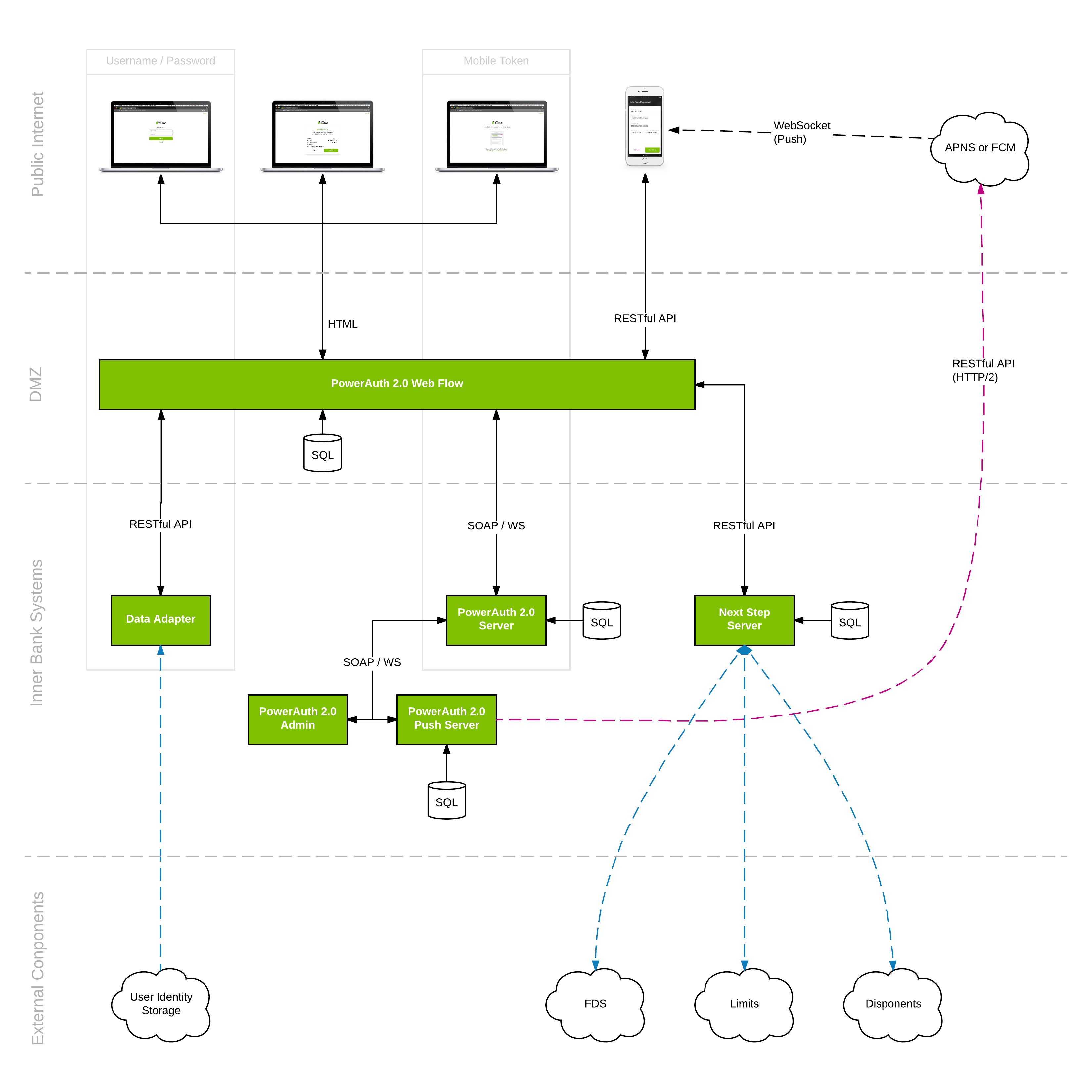
Web Flow architecture diagram:

Web Flow Architecture diagram in higher resolution
The Web Flow application consists of following components:
- PowerAuth Web Flow - a public internet facing web application which provides authentication and authorization services to secure target web application, the user interacts with this application using web browser
- Next Step Server - an internally deployed application which handles logic of resolving the next authentication/authorization step for Web Flow
- Data Adapter - an internally deployed application which handles user authentication, provides access to user profile from client backend systems (marked as User Identity Storage on the diagram), triggers delivery of SMS messages and notifies backend systems about operation changes
- Mobile Token - mobile application deployed on user device (iOS or Android), the user interacts with this application during the PowerAuth mobile token authorization step
- PowerAuth Server - an internally deployed application which serves as a backend providing security services for Web Flow (activation management, signature verification, token verification, etc.)
- PowerAuth Push Server - an internally deployed application which handles push message notifications to mobile clients (iOS or Android) for authorization of operations on user mobile devices
- PowerAuth Admin - an internally deployed application which is used to administer PowerAuth server
Overview
Applications
- Web Flow Server
- Next Step Server
- Data Adapter
- Mobile Token
- PowerAuth Server
- PowerAuth Admin
- PowerAuth Push Server
REST APIs
- NextStep Server REST API Reference
- Data Adapter REST API Reference
- Web Flow REST API Reference
- Mobile Push Registration API
- Mobile Token REST API Reference
Deployment
Customizing Web Flow
- Customizing Web Flow Appearance
- Implementing Data Adapter Interface
- Web Flow Configuration
- Configuring Next Step Definitions
- Customizing Operation Form Data
- Mobile Token Configuration
Technical Notes
Development
Releases