-
Notifications
You must be signed in to change notification settings - Fork 8
DIY ATmega4809 HV UPDI Programmer
The firmware here supports using MCUs in the ATmega4809 Product Family as a HV UPDI programmer. This includes the ATmega4809, ATmega4808, ATmega3209, ATmega3208, ATmega1609, ATmega1608, ATmega809 and ATmega808 devices. Just use a breakout board or development board for the host MCU. If you use any 5V USB serial adapter or IC with an RTS or DTR signal, an auto reset circuit and use a bootloader option in megaTinyCore, you'll be able to use the HV programmer like a regular Arduino board to upload sketches to the target or update the programmer's firmware.
| Click image to enlarge |
|---|
|
 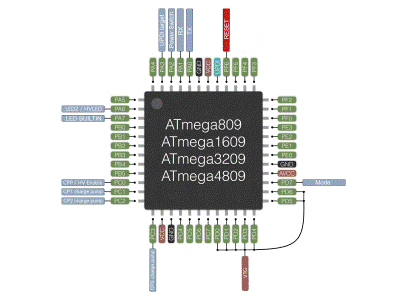
|
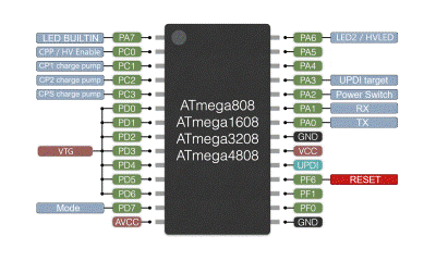
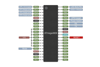
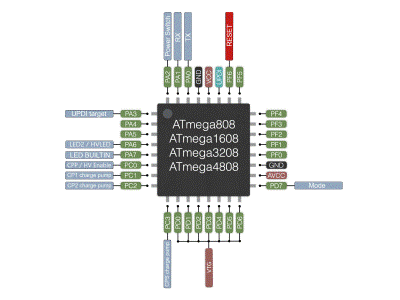
| Pin | Name | Type | Description |
|---|---|---|---|
| PA0 | TX | Output | Serial communication to USB serial IC |
| PA1 | RX | Input | Serial communication to USB serial IC |
| PA2 | Power Switch | Output | Enable for power switch controlling target power cycle, active high |
| PA3 | UPDI target | Bidirectional | Target UPDI programming |
| PA6 | LED2/HVLED | Output | Used to indicate NVM version or UPDI enable 12V pulse |
| PA7 | LED BUILTIN | Output | Active during programming and pulses upon release of reset |
| PC0 | CPP/HV Enable | Output | Charge pump power, normally low, high during HV UPDI enable pulse |
| PC1 | CP1 charge pump | Output | Charge pump Clock 1, 413kHz during UPDI enable |
| PC2 | CP2 charge pump | Output | Charge pump Clock 2, 413kHz during UPDI enable |
| PC3 | CPS charge pump | Output | Charge pump shutdown, normally high, low during UPDI enable pulse |
| PD0-PD5 | VTG | Output | Provides target power and power cycle |
| PD6 | VTG | Input | Senses target voltage for overload detection, 8-bit ADC |
| PD7 | Mode | Input | Mode selection, 8-bit ADC |
| PF6 | RESET | Input | Reset input, pullup enabled, active low |
No full schematic provided as you may want to create your own custom board or prototype. Refer to the schematics and datasheets provided with your chosen components. See the DIY ATtiny HV UPDI programmer page for additional circuit examples.
-
Install megaCoreX (follow their installation instructions)
-
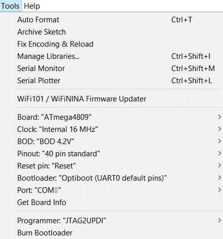
In Arduino "Tools", select the board settings as shown:
-
Connect a UPDI programmer to the Firmware Header and install the auto-reset capacitor.
-
Run "Burn Bootloader"
-
Get the HV Programmer Firmware
● Click on the green "Clone or download" button, then select "Download ZIP".
● Unzip this file in a folder on your PC, then open the sketch "jtag2.updi.ino" into the Arduino IDE.
● Select Sketch > Upload using Programmer, then disconnect the auto-reset capacitor.
You can now use the HV UPDI Programmer to "Burn Bootloader" or to "Upload using Programmer" to the target MCU using the serial port. Make sure to choose the appropriate board, chip and port setting for the target device.
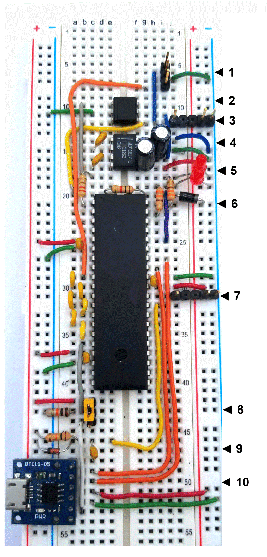
- Pins top to bottom are UPDI target, GND, T5V (PORTD with power cycle)
- Need to remove auto-reset capacitor.
- Pins left to right are UPDI target, 5V (USB), GND
- Need to remove auto-reset capacitor.
- Top LED: LED_BUILTIN (Programing Activity and Target OVL Status)
- Bottom LED: HV Pulse
- Schottky (1N5817)
- Pins left to right are UPDI, 5V (USB), GND
- Need to install auto-reset capacitor
- Jumper 1-2 = PCHV mode (shown)
- Jumper 2-3 = HV mode
- Jumper removed = UPDI mode
Pins 1-5 (top to bottom) are:
- DTR
- RX
- TX
- 5V
- 3.3V
