8. How to make the optogenetic LED probe
Hardware - Firmware - Software
This is a guide to assemble a LED probe with a SMD LED with case size 0402. You need the following materials and tools:
- Tweezers for cutting (540-2029 at RS components) and picking (660-9511 at RS components)
- Quick Set Epoxy (132-605 at RS components)
- Enamel prototype wiring (5017233 at Farnell)
- Alcohol and flux cleaner.
- Tape non-permanent.
- SMD holder.
- 1 NINscope
- 850-10-050-10-001101 Mill-Max connector (split into 2 pin headers)

SMD holder

Hold the SMD LED with the SMD holder. Tin one pad of the SMD LED.
Tin one end of the pencil wires and solder it to the pad of the SMD LED.

Tape the wire and remove the SMD holder. Solder the next pencil wire to the other pad. Remove the flux with flux remover and clean it with alcohol.

Gently bend the wires towards the center of the SMD LED.

Add epoxy to the back of the LED with the wires to isolate and fix the attachment. Cut the wires to required length and solder them to the mill-max connector.

Attach the LED to a NINscope and press the stimulate button. If this does not turn on the LED swap the polarity of the connection and try again. Mark a side of the connector with white paint(or Tipp-Ex) to mark the correct polarity.

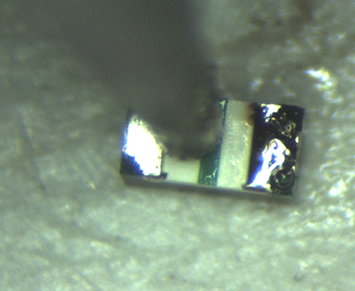
Below a picture with wires to one side.

