Homing and absolute position management
When the system powers up, it doesn't know where the motor is currently positioned. It could be pointing to various directions depending on the timing of the last time the system was shut off.
Also, if an external force exceeding the limit is applied to the stepper motor, the step will slip out of alignment (stall). If this happens, the motor will continue to work with a misalignment between the programmed and physical positions.
Therefore, applications that have a position or orientation must use sensors to detect a reference position at startup or periodically. This action is called homing.
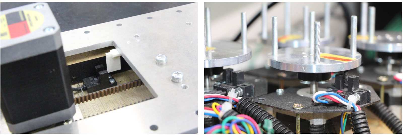
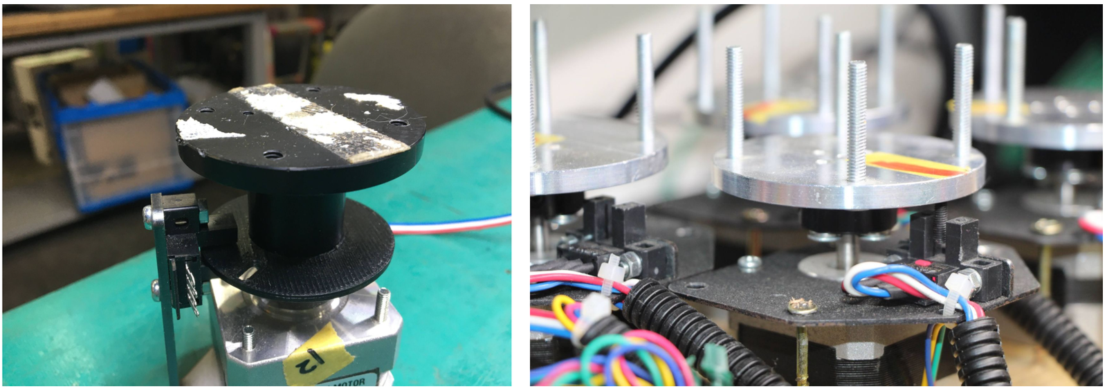
Photointerrupters are often used as home sensors. On the left, a white resin attached to the slider blocks the photointerrupter's light-emitting and light-receiving parts. The right side is an example of a rotary table, where the photo interrupter responds to the black screws.
Other devices are also used, such as microswitches, or photoelectric sensors.
STEP400 has two connectors for each axis, HOME and LIMIT, which can be connected to sensors and switches. Also 5V of power supply is supplied to each connector for sensors.
STEP400 is connected directly to the motor driver chip and can be used in conjunction with the driver's homing function. Usually, this connector is used for the home sensor.
Some applications may require two sensors. For example, a slider has a limited operating range, and if it stalls during operation, it may collide with either end. In such cases, installing sensors on both ends of the slider will prevent collisions.
The motor can be forced to stop when these pins respond, but these can also be used as a simple switch input separated from the motor operation. For example, you can connect a push button to them and press to receive an OSC message.
STEP400 has the following homing commands inherited from the Motor Driver Chip PowerSTEP01.
First, use this command to move towards the home sensor. The motor will stop with deceleration slope when the home sensor reacts (if it has been set up as such).
-> /goUntil
The position at which the motor stops is the home! However, strictly speaking, the /goUnitl command does not stop immediately, but stop after deceleration is completed, so it begins to stop from the point at which the sensor responds. This command slowly moves in the opposite direction from the current position and stops immediately when the sensor is no longer responsive.
-> /releaseSw
Both commands can be set to reset the current position to zero as soon as the sensor responds. -> /setHomeSwMode
See this video for an example of these commands and their operation. https://youtu.be/AydxbL6-a_g
Let's consider "sensors react" a little more strictly. The pin assignments of HOME and LIMIT connectors are as follows.
| Pin number | Function |
|---|---|
| 1 | GND |
| 2 | Switch/Sensor input |
| 3 | 5V Power Output |
Each sensor pin on HOME and LIMIT is pulled up with 3.3V. To connect the switch, connect the GND (#1) and the sensor terminal (#2). When the switch is pressed, it is connected to the GND pin and the voltage drops from 3.3V to 0V. When the voltage changes from HIGH level to LOW level (a.k.a. Falling Edge), the sensor is considered to have responded.
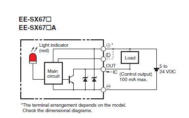
Let's take the sensor EE-SX671A as an example, where the connection is as follows:
| Pin number | Function | Sensor pin |
|---|---|---|
| 1 | GND | - |
| 2 | Switch/Sensor input | OUT |
| 3 | 5V Power Output | + |
This is the part you need to consider carefully before shopping for a sensor.
In the case of the left picture, the light enters the sensor at the home position, but in the picture on the right, the light is blocked at the home position.
There are two types of sensors, one that turns on when light enters and one that turns on when light is interrupted. In the case of the above Omron sensor, the action is toggled by shorting out the "L" terminal and the "+" terminal.
The structure and sensor must be combined in such a way that the sensor pin goes from HIGH to LOW at the home position.
In the example of the picture above, the response position of the home sensor will differ between clockwise and counterclockwise depending on the size of the hole in the left rotary table. In STEP400, both HIGH to LOW and LOW to HIGH changes of the home sensor can be notified by an OSC message. This message also includes the rotation direction, so you can align the home position if you make a case for each rotation direction.
-> /enableHomeSwReport