-
Notifications
You must be signed in to change notification settings - Fork 16
Infrared Sensor
Infrared Sensor model 1838 was used for Peppy player. The sensor output signal can be connected to any spare GPIO pin. I connected sensor output to the GPIO pin #23 as it's not used neither by Amp+ nor by touchscreen. It was chosen because it's located close to the Ground pin. Therefore it's easier to make ribbon cable for this connection - those wires in the cable will be located next to each other.
The sensor's power pin can be connected either to +3.3V or +5V. Originally I connected it to +3.3V. That caused some issues. For example, remote control stopped working when USB WiFi dongle was connected to the Raspberry Pi. Also there were some glitches in the software even with Ethernet network cable connected instead of USB dongle. All issues gone when the sensor's power pin was connected to +5V instead of +3.3V. To be on the safe side 1KOhm resistor was connected in series to the pin which goes to GPIO.

The sensor was mounted above the touchscreen right in the middle of the front panel. The length of connecting cable/wires is not so critical just don't make it too long.

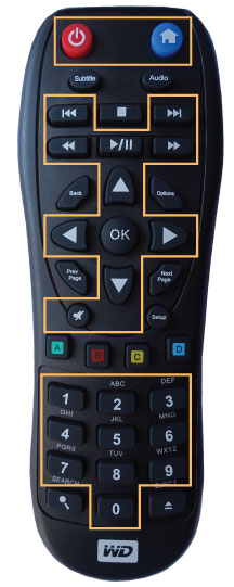
Any infrared remote could be used to control Peppy player. I had a spare remote from WD TV Live player so I configured the Peppy player to use that remote. The separate chapter will explain how to configure a remote control for Raspberry Pi.
All buttons required to control Peppy player were outlined in the following image:

The front panel of the Peppy player is made of the black opaque acrylic glass which blocks infrared signal. That's why the small hole was drilled in the front panel and round window created from a transparent acrylic glass was inserted into that hole and glued to the panel.

- Peppy Players
- Peppy Home
- Hardware
- Audio Players
- Software
- Installation Guide
- Updating Guide
- Peppy Configuration
- Languages
- Scripts
- Voice Assistant
-
Peppy Player UI
- About
- Home Screen
- Radio Player
- Radio Groups
- Radio Favorites
- Radio Browser
- File Browser
- File Menu
- Quick Configuration
- File Player
- Audiobooks Player
- Audiobooks Browser
- Stream
- Podcasts Player
- Podcasts Browser
- AirPlay
- Spotify Connect
- Bluetooth Sink
- Jukebox
- Archive
- Equalizer
- Timer
- Language
- Network
- Headless Mode
- Resolution
- Recursive Playback
- Playback Order
- Information
- Background
- Icons
- Fonts
- Player Screen
- Image Viewer
- Switch
- Collection
- Catalog
- YA Streams
- Web UI
- Screensavers
- Woodware
- Sketches